
Part 2 of 2: Developments in pusher seal technology
by Richard Smith, Director, AESSEAL plc, Rotherham, England and Heinz P. Bloch, Consulting Engineer, Westminster, Colorado 80031.
Although seal face cooling and the other vital requirements discussed in Part 1 of this article (Pump Industry magazine, May 2014) may often appear to be at odds with each other, innovative designs are now available to satisfy all criteria. Computational flow techniques (CFD) and testing have facilitated an understanding of best available solutions that don’t require compromise. All underlying design concepts discussed in this article have been fully validated in field studies.
Achieving seal balance
One method of achieving seal balance involves placing O-rings on the outside of the seal faces. This is now common practice in the chemical process industries. Making the sleeve also serve as the face holder is now possible with modern computer numerically controlled (CNC) machining techniques.
These design and manufacturing techniques facilitate a more compact design, open up the inner seal envelope and provide a deflector baffle (Figure 1). Separating the barrier flow inlet and outlet causes the cooler barrier fluid to migrate towards the inner seal faces and can be critically important to promoting extended mechanical seal life.
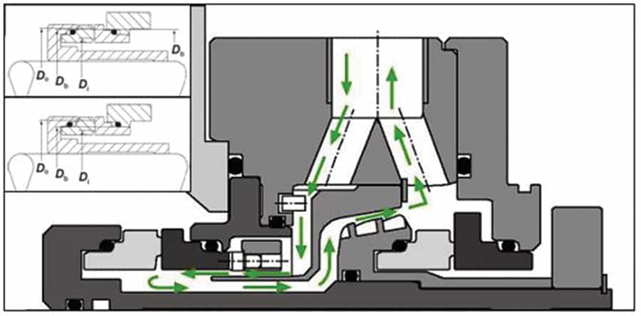
Figure 1. Flow of barrier fluid with deflector baffle. Flowrate increases are made possible by the tapered pumping device shown here (www.aesseal.com).
The exact configuration of the deflector baffle shown schematically in Figures 5 (Part 1) and 1 (Part 2) was actually refined and optimised through the use of modern flow optimisation techniques, typically called computational fluid dynamics (CFD). The before-versus-after results are shown in Figure 2.
Since it is, of course, desirable to maximise fluid flow in contact with the inboard seal faces, the end of the deflector was re-profiled to a triangular sharp edge. The analysis plotted in Figure 2 indicates radial motion next to the extremity of the deflector. This re-circulation reduces the flow path and prevents some fluid close to the deflector nose from escaping before even reaching the seal faces. Compared with the original round shape, the triangular sharp edge shape promotes vortex motion and redirects additional coolant flow to the seal faces.
-

- Figure 2a. Deflector performance after making modifications for flow optimisation.
-

- Figure 2b. Deflector performance before flow optimisation.
Circulation device performance for API Plan 52 and 53 systems
Dual wet seal barrier fluid circulation can be achieved by external means per API Plan 54. It can also be achieved by internal circulating devices per API Plans 53 a, b, and c, and also per API Plan 52 (see Refs. 1 and 2; also Bloch/Budris, Pump User’s Handbook, 4th Edition, 2013). All of these seal flush plans are available from recent editions of API 682; virtually every plan conveys the need to ensure cooling of the seal faces. Effective seal cooling depends upon the barrier fluid circulation devices’ efficiency. Internal devices are part of the seal cartridge and their performance can be affected by many factors, summarised in Table 1.
|
Circulating or pumping device design |
|
Direction of rotation |
|
Seal size |
|
Seal type |
|
Shaft speed |
|
Barrier fluid density |
|
Barrier fluid viscosity |
|
Barrier fluid containment vessel (or cooler) |
|
Seal cavity flow path, concentricity, contour |
|
Gland port orientation ports: top/bottom, tangential |
|
Connecting pipe size & layout (bends/distances) |
|
Fittings connections & roughness of pipe bore |
Table 1. Factors that can affect circulation flow.
Traditional internal circulating devices (Figures 3a and 3b) fall into two groups, parallel slot (castellation, Figure 3a) and helical vane (Figure 3b). Parallel slot devices induce radial flow and must be positioned adjacent to the barrier outlet orifice; they can be bi-directional only if used with radial ports. Helical vane devices are unidirectional, provide axial flow, and are less dependent on port proximity.
-

- Figure 3a. Parallel slot pumping device.
-

- Figure 3b. Helical pumping device.
-

- Figure 3c. Tapered vane bi-directional pumping ring.
However, the use of multi-axis CNC machine tools has given designers far more freedom to devise considerably more efficient arrangements. Figure 3c illustrates a very important option that now presents itself. Here, a modern bi-directional large clearance “tapered vane” pumping ring provides much-improved circulation.
The head versus flow performance of a 100 mm seal with the three different pumping devices in Figure 3 is plotted in Figure 4. The tapered vane device excels with its higher head and higher flow capability.
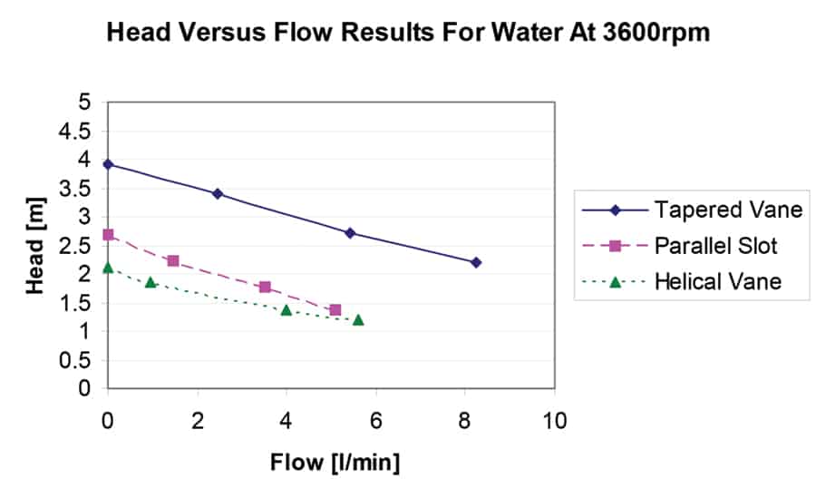
Figure 4. Head versus flow performance of a 100 mm seal with the three different pumping devices (shown earlier in Figure 3).
Practical application and limitations of circulating devices
Tangential porting arrangements can offer improved performance on all three types of devices and utilising this feature on large between-bearing pumps is often straightforward. On smaller units port orientation can be more problematic since gland stud position and pump frame casting will often interfere. Regardless of the pumping device chosen, its respective performance can be optimised by modifying the internal cavity. Suitably positioned cutwaters and eccentric or taper-bored seal environments (pump housings) merit attention. Due to gland plate machining costs these optimisation practices tend to be found primarily on engineered API-610 compliant pumps.
Reductions in internal radial clearance can also improve device performance. However, there are safety implications and sufficient clearance is highly desirable to prevent contact between rotating and stationary components. While not normally occurring, such contact is possible under fault conditions. For many years API-682 had specified a minimum radial clearance of 1.5 mm (Ref. 1). But in their quest for increased device efficiency, some seal manufacturers lobbied for reduced clearances, although unduly small internal clearances tend to impede adequate thermosiphon action when the shaft is not rotating. It should be noted that such fluid flow motion (i.e. thermosiphoning), is required to prevent the seal overheating just after shutdown (when a pump will still be at full temperature) or during warm up.
The flow required in actual service depends largely on the amount of heat that must be removed from the seal by the barrier fluid system. Formulas for seal face temperature heat generation and heat soak from the process to the seal chamber are widely published. On small higher temperature pumps the heat load on the seal barrier system will primarily be thermal soak and the cooling requirements are little affected by changes in shaft speed.
As with any pump impeller, the performance of a circulating device is a function of its diameter and shaft rotational speed. Performance becomes critical to seal reliability on smaller pumps and those operating at four-pole motor speeds or with variable speed drives. Circulating devices must operate efficiently at lower speed on smaller shafts with large clearances and radial porting. Well-engineered circulating devices represent the widest potential application group. Bi-directional designs (Figures 1 and 3c) help eliminate installation errors on between-bearing pumps and can reduce spare parts inventory requirements.
The original tapered vane bi-directional device of Figures 1 and 3c has been in successful commercial service since 1999. Notice that the vanes in early designs were straight. However, research into vane profiles and vane angles has subsequently allowed flow increases of up to 40 per cent. In fact, the vanes furnished after 2011 are contoured into a “swan’s neck” shape, which prevents reverse flow on the back edge of the vane. The performance of this device with its “swan-neck” vanes is virtually equal to that of a similarly configured unidirectional tapered vane. It has been tested at different shaft diameters and shaft speeds. As mentioned above, the relatively liberal radial clearances of 1.5 mm (0.060 in) between the rotor and stator are of interest. The design thus fully conforms to Ref. 1 and best reduces the risk of seal-internal stationary components being inadvertently contacted by seal-internal rotating devices. Test results obtained with a 50 mm ‘swan-neck’ tapered pumping device design (typical of many medium-size pumps) are readily available from www.aesseal.com.
Case studies involving dual mechanical seals
Case studies where implementing some of the discussed design elements has resulted in improved reliability are always of interest.
Face-to-back replacement of back-to-back configuration
There are many published examples that demonstrate improved reliability after replacing older back-to-back seals with modern face-to-back geometries. For instance, back-to-back seals had been installed in circulation pumps used on industrial laundry machinery manufactured in the UK by Thomas Broadbent and Sons, Ltd.
The duty for these ISO-compliant pumps (Ref. 1) would be considered “light” in most industries. They operate at 85°C with a seal chamber pressure of 3 bar and have two seal sizes, 28 mm and 65 mm. The pumped fluid, however, was contaminated with fibers typically known as “lint”. These fibers would enter the seal chamber and become packed near the inside diameter of the inner seal faces. The resulting seal face hang-up caused premature failure. After retrofitting dual seals with face-to-back orientation, the pump MTBF (mean-time-between-failures) improved more than six-fold.
Replacement of back-to-back with advanced face-to-back technology including flow deflector baffle
A complex reactor circulation duty at a chemical plant in Wales, UK, demanded that a twin-screw pump (made by Albany Engineering) be used and fitted with four dual seals. Conditions included process temperatures between 25-180°C, seal size 54 mm, seal chamber pressures ranging from slight vacuum to 3.5 bar, viscosities ranging from 0.5cP to 5000cP, and shaft speeds ranging from 180 to 1500 rpm.
Light silicon oil was selected as the barrier fluid. This had proven problematic on other applications due to its poor lubricity and heat transfer properties at elevated temperatures. However, silicon oil had to be used for reasons of compatibility with the process fluid. An external pumping device Plan 54 configuration (Refs. 1 and 2) was selected for these variable-speed driven pumps.
Several variants of back-to-back bellows cartridge seals were tested, but failures occurred typically after six months. These failures were primarily attributed to pressure reversal issues, as described earlier. Since then, face-to-back seals with deflector baffles have been successfully used at this facility, replacing both traditional face-to-back and back-to-back designs in these screw pumps. Not only have the pumps achieved extended process runs in excess of two years, but the seal faces were still in pristine condition when examined after almost three years.
Traditional face-to-back vs. advanced face-to-back with internal pumping Plan 53 in an automotive paint facility
Superior coating technologies are used in the automotive industry. Today, automobile body corrosion is virtually unheard of. One of the reasons for this is full immersion in primer dip tanks with an electrical charge applied. However, facilities were challenged by sealing issues in the electro-coat primer circulation pumps. The paint contains sub-micron abrasive particles, making it necessary to use hard-faced wear-resistant materials on the inner seal. The paint temperature has to be maintained near a process temperature of 25°C ±10°C. Upwards excursions in temperature are risky and could cause paint to rapidly congeal. Dual seals are used for this sealing duty and ultra-filtrate, essentially de-ionised water with other chemicals acting as a thinner, is used as a compatible barrier fluid.
End suction pumps with a 50 mm shaft are employed. At first, seal cooling and poor circulation device efficiency had prevented reliable operation of conventional face-to-back seals and API Plan 53a systems (Refs. 1 and 2). The paint is tenacious and tends to overcome the barrier fluid film pressure between the inner seal faces. Heat generated by these faces causes the paint to congeal or polymerise. As the paint particles migrate, they cause the seal face gap to widen and, although the faces are undamaged, excessive leakage results. While it would seem logical to simply increase the barrier fluid pressure, this would increase temperature generation and the added heat load would merely accelerate problem development.
Reliable sealing has traditionally been achieved by using moving pressurised barrier fluids at the high flow rates achievable with API Plan 54 (Refs. 1 and 2). However, these relatively complex external barrier fluid circuits often require instrumentation ensuring that equal flow reaches each seal in the many pumps installed for parallel operation. Individual seal fault diagnostics can be difficult and cost-intensive with Plan 54 because a centralised pressure source provides external barrier fluid circulation to several pump sets.
These concerns then prompted plant designers and operators to seek alternative solutions. Modern face-to-back cartridge seals with high efficiency circulation devices and barrier fluid flow separation baffles will give superior performance in such duties with API Plan 53a (Refs 1 and 2). API Plan 53a systems offer many advantages in terms of cost and simplicity and these systems have been successfully installed in five automotive plants in Europe and on other continents. In fact, advanced face-to-back seals have, as of 2012, seen flawless operation for over seven years at one UK automotive plant.
Experience shows that mechanical seal technology continues to develop and that application of sound principles is useful in all sectors of industry. Highly reliable face-to-back designs are now available with enhanced cooling features. These developments have greatly expanded the application range for this advantageous dual-seal configuration. Well-proven developments combine API Plan 53a with tapered vane pumping devices. These devices certainly merit close consideration in many pumping services.
Note: Our footnote again mentions the Pump User’s Handbook (4th Edition, 2013) because flush plans of interest to dual seals can be found in this text. Another source is API 682 and websites including API, AESSEAL, and others. The co-authors again acknowledge the kind permission of API and the hard-working, experienced volunteers who keep the standards up-to-date.
References (for Part 2 of article):
1. API Standard 682/3rd Edition; also ISO 21049, (2004): Shaft Sealing Systems for Centrifugal and Rotary Pumps, API (American Petroleum Institute), Alexandria, VA.
2. API Standard 682/2nd Edition, (2002): Shaft Sealing Systems for Centrifugal and Rotary Pumps, API (American Petroleum Institute), Alexandria, VA.
Find Seals Related Companies In The Pump Industry Capability Guide


-
Lubrication update for electric motors
By Heinz P. Bloch, PE, Process Machinery Consulting Australia’s largest oil refinery, BP’s Kwinana, is among the best-of-class refineries...
-
Hydraulic Institute technical meeting
Registration for the 2013 Hydraulic Institute (HI) Technical meeting is now open. This year’s meeting will take place June...
-
Pump school: predicting performance with speed variations
Question: How do I predict changes in pump performance with variations in speed? Answer: There are fundamental laws which can...
-
New sewer main and pump station expand Heathcote network
Sixteen homes are the first round of properties that are now able to connect to a newly expanded sewer...
-
Efficient operations of pump systems (part 5)
The PIA’s Australian Pump Technical Handbook is a cornerstone text for the Australian pump industry and, in our opinion,...
-
ZETRIX: Triple offset valves by ARI Armaturen, Germany
The role of plant management is to operate both efficiently and safely. Just as blood is pumped around our...
-
Faulty pump causes water pollution
A failed injection pump discharge isolating valve at Macquarie AGL’s Bayswater Power Station has caused water pollution in nearby...
-
Selecting & applying slurry pumps
The PIA’s Australian Pump Technical Handbook is a cornerstone text for the Australian pump industry and, in our opinion,...