


Part 1 of 2: Comparing arrangements and reconciling requirements
By Richard Smith, Director, AESSEAL plc, Rotherham, England, and Heinz P. Bloch, Consulting Engineer, Westminster, Colorado [email protected]
Mechanical seal designers face challenges when developing dual seals for a multitude of users and industries. Although originally aimed at the Hydrocarbon Processing Industry, the American Petroleum Institute’s Seal Standard (API-682 / ISO 21049) is very widely used because it lists and explains many universally applicable requirements.
Dual seal arrangements
Dual seals are increasingly important in many industries, including hydrocarbon processing. Driving this are plant hazard safety requirements, reductions in allowable fugitive emissions and the quest for increased equipment uptime. API- 682 / 3rd Edition (Ref. 1) and its appendix material collectively describe pressurized seal geometries as Arrangement 3. This arrangement comprises two seals per cartridge assembly and an externally supplied pressurized barrier fluid. Taken together, the seal layout and flush arrangement create a beneficial and life-extending seal environment.
The different configurations for Arrangement 3 are described by API-682 as:
- Face-to-back dual seal in which one mating ring is mounted between the two flexible elements and one flexible element is mounted between the two mating rings or seats (Figure 1a).
- Back-to-back dual seal in which both of the flexible elements are mounted between the mating rings (Figure 1b).
- Face-to-face dual seal in which both of the mating seal rings are mounted between the flexible elements (Figure 1c).
However, the description “dual seal” is inadequate. It should be pointed out that the principal attribute of the face-to-back (“FB”, Figure 1a) configuration is locating the process fluid (pumpage) on the outer diameter of the inside set of seal faces. In the other two configurations the process liquid is on the inside diameter of the inside set of seal faces. Note that in this context an outside-facing set of faces would come into contact with the atmosphere.
Face-to-back arrangements are preferred, although back-to-back and face-to-face orientations are offered as purchaser’s options. In API-682, non-pressurized dual seals are called Arrangement 2 and face-to-back is the only arrangement option available in the API 682 standard.
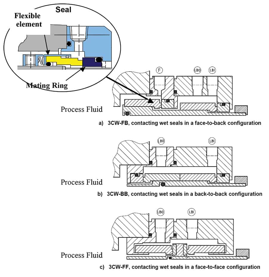
Figure 1: Three styles of dual face mechanical seals for pumps
Advantages and disadvantages of back-to-back and face-to-face seal configurations
In the hydrocarbon processing industries, back-to-back and face-to-face configurations are widely represented. They can potentially offer higher levels of performance-in large measure attributable to the cooling effect of barrier fluid flowing over both inner and outer seals. However, there also are disadvantages.
The main shortcoming of back-to-back and face-to-face configurations is that the process fluid is on the inside diameter of the seal faces. Centrifugal force action tends to throw any entrained abrasive solids towards the seal faces, which increases the potential for damage. The “dead zone” formed by a small volume of process fluid underneath the inner seal increases the probability of trapping fluid. Trapped fluids tend to congeal and solids are likely to accumulate in dead zone spaces. As the secondary O-ring will then move over a deposit-affected region of the sleeves (Figure 2), “hang up” is more likely to occur.
The application of reverse balance (which will be explained below) can be more difficult with back-to-back designs. Upset conditions such as loss of barrier fluid pressure or increases in process pressure can adversely affect back-to-back configurations. Positive retention of the inner-seal mating ring can be difficult to accomplish since there will always be unavoidable dimensional constraints of associated hardware and seal chambers.
So, unless properly retained, thrust forces acting during pressure reversal may cause a ring to become dislodged. Also, with some designs, reverse pressure loading will apply a hydraulic force to the inner seal spring plate. This reverse pressure then tends to open the seal faces.
These concerns have, over the past two decades, prompted chemical process industries to move toward face-to-back designs. Overall seal reliability has improved with face-to-back configurations.

Figure 2: Explaining the potential for “hang-up”

Figure 3: O-ring movement with pressure reversals
Advantages of face-to-back seal configurations
Face-to-back configurations overcome virtually all the weaknesses of other designs with pumpage on the outside diameter of the seal faces. The preference for this configuration is noted by API-682 and is summarized below: ‘The advantages of the series configuration are that abrasive contamination is centrifuged and has less effect on the inner seal.’
A further note supports the case: ‘Liquid barrier seal designs arranged such that the process fluid is on the OD of the seal faces will help to minimize solids accumulation on the faces and minimize hang-up.’
Dual balance is easier to incorporate in this configuration and the seal O-ring can be located so as to permit it to move to either side of the groove. This then supports a closing force regardless of the direction of pressure. Mating rings can be simply retained either positively or, with more modern designs, hydraulically (Figure 1b). Pressure reversal capability provides for greater safety; it increases the degree of tolerance for many process upset or loss of barrier fluid conditions. Again, API-682 reinforces this point in a note:
‘In the event of a loss of barrier fluid pressure, the seal will behave like an Arrangement 2’
Figure 2 illustrates O-ring retention and movement with pressure reversals.
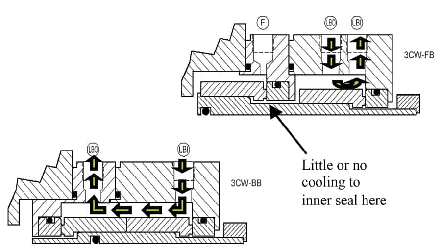
Fig. 4: Barrier fluid cooling comparison face-to-back (right) versus back-to-back (below)
Disadvantages of conventional face-to-back configurations
Of major concern in face-to-back designs is cooling of the inner seal. Seal designers have typically approached the issue by mounting component seals with adaptive hardware (sleeve and gland) to form a cartridge. However, the barrier fluid flow path to the inner seal is compromised by a region of low or zero flow. The temperature in these stagnant areas will be elevated by heat soak and face-generated heat. The 2nd Edition of API-682 very eloquently provides a warning (Ref. 2):
‘Restricted seal chamber dimensions and the resulting cartridge hardware construction can affect the ability of the barrier fluid flush to adequately cool the inner seal. Inadequate cooling of the inner seal can result in reduced seal reliability. Selection of a back-to-back or face-to-face configuration may resolve an inner seal cooling problem.’
Accordingly, the challenge for seal designers is to provide both a seal with optimized cooling and to simultaneously provide resistance to “hang up” and pressure reversal.
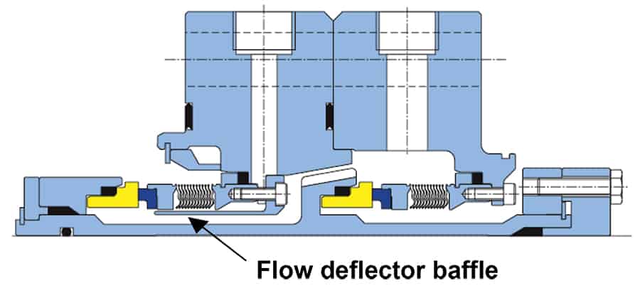
Figure 5: Face-to-back bellows seal with deflector baffle. This baffle guides the barrier fluid towards the seal faces (Source: AESSEAL plc., Rotherham, UK, and Rockford, TN)
Deflector baffle developments
An ordinary face-to-back (“FB”, upper right) seal would receive little or no cooling at the inner seal faces. That fact drove technology innovation to improve inner seal cooling. Superior cooling can now be achieved by incorporating a high performance circulating device and flow deflector baffle in dual seals. The deflector baffle in Figure. 5 diverts the barrier fluid flow to the inner seal; this provides cooling to the inner seal faces and represents an elegant solution to the dual seal challenge: good cooling and superior containment in a small dimensional envelope.
Deflector baffles have long been employed on single high-temperature seals connected to quench stream. However, restrictions in seal chamber dimensions and somewhat large cross-section of conventional dual balanced pusher seals have generally inhibited the more widespread use of deflector baffles. Except for bellows seals with their traditionally smaller cross-sections (Figure 5), incorporating deflectors has generally been limited to “engineered specials” rather than off-the shelf designs. Still, in applications where more space is available the deflector baffles can be optimally shaped and contoured. This contouring is now much more widely available from the true innovators. Proper contouring now guides the maximum amount of barrier fluid to the regions from which heat must be removed or where cooling is of greatest benefit.
In other words, well-engineered deflector baffles are now part of superior dual mechanical seal designs where they determine flow direction. Also, there needs to be flow-rate optimization for barrier fluids.
Part 2 will elaborate on modern deflector baffles and pumping devices.
References
1. API Standard 682/3rd Edition; also ISO 21049, (2004): “Shaft Sealing Systems for Centrifugal and Rotary Pumps,” API (American Petroleum Institute), Alexandria, VA
2. API Standard 682/2nd Edition, (2002): “Shaft Sealing Systems for Centrifugal and Rotary Pumps,” API (American Petroleum Institute), Alexandria, VA
Find Seals Related Companies In The Pump Industry Capability Guide


-
VSDs lead irrigation efficiency measures for Gunnedah cropping enterprise
Working with the NSW Farmers’ Energy Team, the Kensal Green farm in Gunnedah identified significant energy saving opportunities over...
-
Forging a new path in 2020 for the PIA
By Eliza Booth, Assistant Editor, Pump Industry Magazine In early November, the PIA council and its members came together...
-
LNG receiving terminals
By David A. Coyle and Vinod Patel, Kellogg Brown and Root, Inc, Houston, Texas Last year we looked at...
-
Standards Australia and PIA seek feedback on ISO 13709:2009
The International Standards Organisation (ISO) has requested feedback, via Standards Australia, on an “aged” pump standard, i.e. a standard...
-
Bringing pressure sewer to small communities
Gippsland Water’s latest project, a 2,700 property sewerage scheme in Loch Sport, Victoria, will resolve environmental and public health...
-
The mining pump market
Australia has one of the world’s largest mining industries and is among the top 5 producers of minerals globally....
-
Successful project management (Part 4)
In previous articles in this series on successful pump project management, Keith Sanders looked at pump system design and...
-
Viscosity
The viscosity of a fluid is the property that tends to resist a shearing force. A detailed discussion on...


