


By Ian Gaffing, John Crane, Fluid Sealing Association Member
The word “slurry” is a very general and broad term used across a wide range of industries. Typically, slurry refers to a fluid containing a significant proportion of solids, abrasives or fibres. Slurries are quantified by their overall specific gravity and are usually described in terms of percentage of solids in the carrier fluid. This percentage ratio is usually expressed as ‘% solids by weight’ or ‘% solids by volume’. Due to the solid matter being more dense than the fluid itself, slurries can have high specific gravities and are often non-Newtonian fluids.
Pumping slurries is common in numerous applications such as mining, pulp and paper, and food processing. These particulate slurry applications or services include, but are not limited to:
- Cement
- Clay
- Gravel
- Ore
- Sand
- Ash
- Bauxite
- Limestone
- Kaolin
The percentage of solids present, the hardness and the size of the particles in the slurry, as well as the characteristics of the carrier fluid itself are key factors that require careful consideration when choosing the appropriate sealing mechanism.
Irrespective of the slurry constituents, the key objectives of a slurry pump seal are to:
- Minimise maintenance, lowering asset operating costs
- Control leakage of fluids
- Improve asset uptime by increasing the reliability of the seal and seal system solution
An overview of typical sealing technologies
Gland packing
Gland packing is an early form of sealing device, in which braided material is formed into rings and compressed axially between a shaft and the stuffing box to provide a basic seal.
As a sealing method, gland packing has several key disadvantages, including relatively high leakage, the need for regular adjustment onsite and high friction, causing increased energy consumption and wear of the shaft sleeve.

Figure 1: An example of gland packing within the stuffing box.
Single seals
Single seals, defined in API682 as arrangement 1, are the simplest and cheapest method of achieving a seal for a high-pressure pump. The mechanical seal faces are lubricated by the process fluid.
For sealing slurries, an API682 Plan 32 flush is recommended. This system provides injection of clean liquid from an external source into the seal chamber (also known as the stuffing box) at a pressure slightly higher than the chamber itself.
As the external fluid flow needs to be high enough to prevent ingress of the slurry, the costs associated with the flush can prove prohibitive.

Figure 2: A typical API Flush Plan 32.
Dual unpressurised seals
Dual unpressurised seals (previously known as tandem seals), defined in API682 as arrangement 2, utilise an unpressurised buffer fluid between two pairs of seal faces.
The inner seal faces are lubricated by the process fluid. Any leakage across the inner seal is absorbed by the buffer fluid and dissipated in a controlled manner.
For slurries, this arrangement leads to contamination of the buffer fluid with solids and abrasion of the seal faces.
To combat this an API Plan 32 would also be recommended for a dual unpressurised seal, with the same drawbacks as a single seal for added fluid expenditure, but with the additional costs of circulating another fluid.

Figure 3: Typical dual pressurised seal pressure arrangement.
Pressurised dual seals
Pressurised dual seals (previously known as double seals), defined in API682 as arrangement 3, utilise a barrier fluid pressurised above the process pressure.
Any leakage across the inner seal face will therefore be from the barrier fluid into the process fluid. The seal faces are lubricated by the clean barrier fluid.
As the leakage across the inner seal faces is clean barrier fluid, abrasive particles from the slurry are flushed away from the seal faces.
This is the most expensive option due to the complications of providing a pressurised barrier fluid system.
However, this option generally offers better reliability than the other two arrangements since seal performance is not dependent on the process fluid for lubrication.

Figure 4: Typical double seal pressure arrangement.
Dynamic lift USP sealing technology
A conventional mechanical seal operates by utilising the higher-pressure fluid as a film between two precision lapped seal faces. The hydrodynamic action of the seal allows a film of usually <1 micrometre to form which lubricates, cools and minimises mechanical contact.
This principle ensures that any leakage across the seal faces occurs from a higher-pressure fluid into a lower-pressure region.
Dynamic lift technology uses grooves on one of the seal faces to generate pressure between the seal rings so that they physically separate and operate in non-contacting mode.
The most well-known use of this is for dry gas seals, where a barrier gas at a higher pressure than the sealed pressure is used to separate the faces.
Dynamic lift USP utilises specially optimised spiral grooves on one of the seal faces to create a pumping effect. The face design generates a positive pressure across the seal face from inside diameter to outside diameter, i.e. from the lower pressure buffer fluid to the higher pressure process fluid in the seal chamber.
This has the effect of raising the pressure of the fluid film between the seal faces to above that of the process. The pumping mechanism creates a controlled flow of buffer fluid from low pressure into the higher-pressure process fluid.
The seal acts like a pressurised dual seal without the need to pressurise a barrier fluid.
The low-pressure buffer fluid is sealed by a containment seal typically operating at the pre-set buffer fluid pressure but capable of containing the sealed chamber pressure in the event of an inboard seal failure.

Figure 5: Typical up-stream pumping pressure arrangement.

Figure 6: USP pressure generation.
Dynamic lift up-stream pumping technology offers many advantages over the traditional dual seal approach:
- The technology is ‘non-contacting’ and therefore the usual pressure-velocity limitations imposed by contacting seals, and the resultant wear, do not apply
- The power consumed is significantly lower than a double or tandem seal arrangement
- The positive flow of clean buffer fluid into the seal chamber can provide a cleaner sealing environment
- Compared to a non-pressurised tandem seal, a USP seal has the advantages of clean fluid lubrication and non-contacting operation
- Compared to a pressurised double seal, a USP seal requires a much simpler support system and reverse pressure is inherently eliminated
- The process fluid is on the outside diameter of the seal faces – solids suspended in the process fluid are centrifuged away from the seal faces and secondary seal area
- Buffer fluid leakage to atmosphere is significantly reduced when compared to a pressurised dual seal – where the outboard seal can often operate with a considerable pressure differential
- The concept allows a simple upgrade of single or multiple seal services where process changes have rendered the process fluid a poor seal lubricant
- In services where the process pressure is variable, or where pressure spikes are likely, the spiral groove constantly regulates against this varying pressure, maintaining a sealing gap at all times
- The non-contacting seal faces generate little heat compared to a conventional solution. The seal faces are cooler and therefore much less likely to encourage scale formation
- In all cases, should sealing integrity of the inboard seal be lost, the outboard seal will safely operate under full duty conditions
- The flush requirement for double or tandem arrangements is often unnecessary with USP due to low heat generation, reducing water usage
- Increased mean time between repair (MTBR)
- Only a simple support system is required with a small footprint
Developing the first high pressure USP seal
The first high pressure USP seal was designed and validated back in 2003, leading to the creation of standard USP product ranges. The initial design focused on an emulsification of oil and water contaminated with varying concentrations of sand.
The 75mm seal design shown in Figure 7 was tested under the following operating conditions:
| Shaft speed: | 3600 rev/min |
| Seal chamber pressure: | 5 to 40 bar(g) |
| Seal chamber temperature: | 70-80°C |
| Process fluid: | Water, water/oil/sand (20% wt. sand) |
| Buffer fluid: | Seawater |

Figure 7: First high pressure USP arrangement.
Figure 8 shows the condition of the seal face components following a 200 hour slurry test. After testing faces were in as-new condition with no wear or contact marking.

Figure 8: Seal faces post slurry testing.
Since this application went live, further development has been performed with designs capable of running at up to 100 bar(g), with laboratory testing performed in excess of 200 bar(g).
Finite Element Analysis and Computational Fluid Dynamics aid with optimisation of seal face parameters.
This allows the design of bespoke engineered solutions when applications fall outside of the standard USP range of products.
Simplified seal support systems
By nature of the design and operation of dynamic lift USP mechanical seals, the required support system complexity is greatly reduced compared to that used with a conventional pressurised dual seal.
Due to a lack of cooling requirement for many designs, the system requirement is simply an elevated tank with an optional automatic fluid top up system. Figures 9 and 10 show the basic support system.

Figure 9: Schematic showing typical piping plan arrangement.

Figure 10: In-situ typical piping plan arrangement.
Case study
Background
Industry: Mining
Site: Mine raw material processing plant
End Product: Kaolin used in pulp and paper, deinking, paints and coatings, adhesives, caulks and sealants
Customer need
- In 2009, a processing plant serving a kaolin mineral mine experienced downtime related to an unreliable pumping process
- When the magnetic process to remove ferrous metal particulate from the kaolin mixture was interrupted, production came to a standstill, cutting into profits
- A pump with braided gland packing could not stand up to the fluid flow volume
- The process plant wanted to move quickly to improve the pump and seal’s costly three-to-six-week mean time between repair (MTBR) track record
- The mine’s parent company, one of the world’s leading mineral producers, looked to its local distributor and John Crane for a solution to the costly maintenance pump application
Application
- The local John Crane Distributor identified the faulty standard seal and packing that were damaged due to vibration and intermittent pump volume flow caused by continuous periodic cavitation
- MTBR for the seal was three to six weeks, each event impeding the process flow throughput volume, ultimately reducing end product flow and output
- The distributor, who also supplied seals for the original project, requested input from John Crane after attending a training session that reviewed the USP’s non-contact technology
- The mine chose a unique and innovative face design to improve the MTBR – dynamic lift USP available only from John Crane
- The non-contacting technology would be less affected by pump flow interruptions and vibration
Solution
- The kaolin mine replaced the existing seal and braided packing with John Crane’s series 5620 series standard double seal, fitted with inboard and outboard pumper mating rings, creating the unique design geometry of the high-pressure USP seal
- The flush line was filtered to >5 microns with an inline filter, deadheaded to seal and the remaining inlet/outlet ports were plugged
- The low-volume, high-pressure USP seal works by propelling a small amount of buffer liquid along the path normally sealed by a mechanical seal face and into the higher-pressure product side
- The 5620 USP seal design greatly reduces seal and equipment wear, utilising a face spiral groove pattern to direct barrier fluid toward the outside diameter, setting up a sealed gap and eliminating physical contact of the faces during operation
- The John Crane 5620 USP seal gave the mill the solution to withstand the intermittent flow and vibration
Summary
Dynamic lift USP sealing technology has been available to the marketplace in various shapes or forms for many years, however it is only in the last ten or 20 years that the technology has been available to allow these designs to operate in more demanding environments.
The technology is an alternative to traditional gland packing or standard mechanical seal arrangements.
As industries are being encouraged to reduce energy and water consumption, improved sealing technology is seen as one method to improve environmental performance.
Due to non-contacting operation, dynamic lift USP sealing technology can assist with lowering overall environmental impact through reduced energy and water consumption, whilst the relative simplicity of the design and operation allows a significant improvement in not only the reliability, but the operating costs of the associated assets.
As user confidence levels continue to develop, dynamic lift USP technology is being applied more frequently to increasingly demanding applications.
Find Seals Related Companies In The Pump Industry Capability Guide

-
State of the Industry in 2017: new opportunities drive optimistic outlook
Recently Pump Industry undertook its fourth annual State of the Industry survey. The survey’s results provide insights into current trends...
-
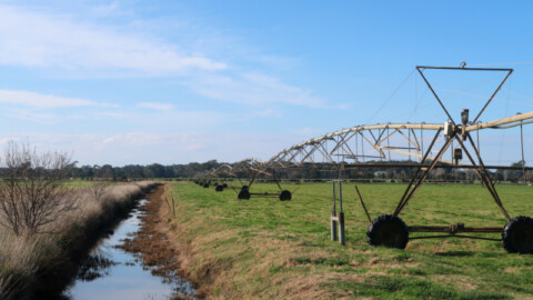
Irrigation overhaul: how pumps helped a dairy farm’s renewable energy transition
Sandra Jefford and Wilco Droppert own and operate Wilandra Farms, an organic dairy farm in the Gippsland region of...
-
Executive Director of Hydraulic Institute to retire
The Hydraulic Institute, North America’s largest pump trade association, recently announced the planned retirement of its long-serving Executive Director...
-
Ticking time bombs!
by Andre Mierzwa, Chief Engineer – FM Global Over the last few years, fire protection servicing providers have seen...
-
Strengthening the PIA in 2018
Last November, the PIA council and its members gathered for the association’s 14th annual general meeting and dinner. Attendees heard...
-
Understanding pump curves – watching Bad Actors
Long-time loyal followers of Pump Industry are likely acquainted with Ron Astall's well-received series of articles on comprehending pump...
-
SAER celebrates 70 years of experience with a new video
Established in 1951 at a time when Italian households were beginning to get running water, the evolution of SAER...
-
Pumped hydro: the next wave of energy storage
Australia’s thermal power capacity is progressively retiring, with almost two thirds of the country’s coal-fired generation capacity expected to...


 sealing technology to slurry pumps)