

By Matthew Thompson – Technical Engineering Manager, Renroc Group (Pumps & Engineering)
Centrifugal pumps are one of the most common pieces of process equipment. In modern process systems there is a requirement for multiple flow conditions to meet process requirements. In times of start-up, shutdown or abnormal process conditions system flow can be greatly reduced and flows through centrifugal pumps may fall below the pump’s minimum flow value.
Pumps operating below minimum flow are unstable due to high thrust loads causing high vibrations, can overheat and cavitate due to the increase in NPSHR at lower flows. Typically 30 per cent of the flow at the pump’s Best Efficiency Point (BEP) must be circulated to avoid these operating conditions. The minimum flow value should be stated by the pump manufacturer. There are multiple ways that minimum flow can be maintained at all times and these are discussed below.
Continuous bypass system
This system installs an orifice plate or series of orifice plates in a bypass line. In this installation at all times the pump minimum flow is bypassed back to the suction tank. By using this system; Pumps are oversized as they are required to pump duty flow and bypass flow, bigger pumps, bigger motors leading to higher capital costs There is a constant waste of power as flow runs through the bypass line unnecessarily. Even when only extra 2kW is required to give this constant bypass flow this equates to 17,520kW of power used per year which at 0.15c/kWh equals $2,628 per year and 19.3 tonnes of CO2 (based on coal power 1.1kg/kWh) This system is no longer best engineering practice in a world concerned with efficiency and sustainability and the wastage can no longer be tolerated. The orifice plates can also have high wear across them due to high fluid velocity and cavitation across the plate.
Controlled bypass systems
This system uses a control valve and instrumentation to divert flow to the bypass only when required. A flow sensor is used to determine low flow which will open the valve using an actuator to control flow back to the suction tank. This system is quite complex and requires many parts to work together which is both difficult to commission and has a higher chance of failure. These systems are often high capital cost and higher maintenance cost as all individual components require periodic maintenance.
VSD Control
Pump systems may also be controlled by VSD allowing for different process conditions. Maintaining minimum flow using VSD requires additional complex and costly electronics. These require cooling and control for the system to work effectively.
Schroedahl Automatic Recirculation Valve
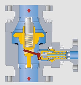
The Schroedahl Valve is designed to keep the pump operating on its pump curve. The Schroedahl ARC Valve provides the most economical and reliable form of pump protection. The valve combines the following 4 components in one; Flow sensing – The check valve is machined to in such a way that it senses process flow and opens accordingly. This check valve then operates the bypass line as it rises and falls. Check valve – The ARC is also a check valve eliminating the need for a separate valve Modulating function – The check valve will open or close based on process flow Pressure reduction without cavitation – Pump pressure is broken down over the bypass insert without cavitation. The Schroedahl ARC valve is fully mechanical and activates by flow sensing reacting to the system flow controlled by a downstream process valve. When no flow to the system is required the check valve will close opening the bypass, this is fully flow controlled based on shaping the check valve correctly. As the system opens and draws flow the check valve will unseat and move vertically sending flow to the system while closing the bypass line. Schroedahl ARC valves are fail safe, in the unlikely event of a failure of the internals the valve will fail in a bypass open position insuring the pump is protected at all times.
Sizing the valve
When sizing the valve the following information is required; Fluid Temperature Specific Gravity / Density Pump duty flow and pump head at this condition Pump minimum flow and pump head at this condition The pump curve is always desirable The flange size and rating of the pump outlet (Ideally the valve should be installed direct on the pump discharge and will be matched to this flange) Material for body (Typically the body material is matched to the pump casing, valve internals are various stainless steels with a minimum 12% Chr) Installation (Vertical is the standard and preferred orientation for the valve, horizontal can be supplied upon request)
Conclusions
The Schroedahl ARC Valve is designed specifically for process conditions to give a reliable fully mechanical check valve/bypass valve. It is best engineering practice for maintaining pump minimum flow giving the most efficient system and best protection.
For further information or to view an animation of the valve in operation click here.
-

- Line diagram of continuous bypass system using orifice plates.
-

- Schroedahl TD series valve.
-

- Cross section of a Schroedahl TDM valve.
Find Valves Related Companies In The Pump Industry Capability Guide


-
Operating pumps at partial capacity: causes of vibration
By Dr Gary Dyson, Managing Director, Hydro Global Engineering Services (UK) and Chandra Verma, Chief Design Engineer, Hydro Australia...
-
Wastewater Summit a feature of Waste Expo Australia
Ensuring the continued supply of safe drinking water is at the forefront of business operations for water organisations across...
-
German researchers develop motorless pumps and self-regulating valves
A research group at Saarland University in Germany, has developed motorless pumps and self-regulating valves — using ultrathin electroactive...
-
Toowoomba valve tender awarded
Toowoomba Regional Council has awarded a valve tender to Promains (Qld) Pty Ltd The tender was for the Supply...
-
What is a diaphragm pump, how it works and when to use one
A diaphragm pump, part of the positive displacement pump family, is a versatile and reliable pump that can be...
-
Tender: Curtis LNG water treatment facilities
Veolia Water Australia Pty Ltd is seeking general expressions of interest from suitably qualified contractors for works on QGC’s three...
-
Pressure recovery in hydraulic systems
by Neel Kaila, Director, Neel Pty Ltd, Nathaniel Brubaker, Engineering Student, Miami University and Robbert Veerman, Technical Consultant At its...


