
By Johan Cilliers, Valve Product Manager, Amiad Water Systems.
Cavitation may be foremost in the minds of any pump system designer, and careful thought may be taken to avoid cavitation and the resulting damage tothe pump(s). However, it is often overlooked or ignored when selecting automatic control valves and their location on the same pipework system.
When a pressure reducing valve automatically reduces a higher inlet pressure to a lower outlet pressure, the combined kinetic- (velocity) and potential (pressure) energy remains the same either side of the valve (law of energy conservation). Water is virtually incompressible, and the flow area at the valve inlet is the same at the valve outlet, hence the flow velocity at the valve inlet is the same as at the valve outlet. The pressure at the valve outlet is however lower than at the valve inlet, and the so-called pressure “loss” is achieved by converting some of the potential energy to heat, but mostly to another form of kinetic energy – vibration, which we experience as “hydro-dynamic noise” being omitted from the vicinity of the valve station as illustrated on Figure A.
As illustrated on Figure B, the flow stream velocity increases as the water passes through the valve seat/seal opening, while at the same time the pressure decreases, up to the “vena contracta”. The “vena contracta” defines a point in the flow stream just downstream of a flow restriction where the flow stream velocity is maximum, and the pressure is at its lowest. Downstream of the vena contracta, the velocity usually decreases back to its original value while the pressure again resumes a value lower than its original value (P1 minus pressure energy “lost” to vibration/noise).
If the minimum pressure at the vena contracta drops below the liquid vapour pressure (-9.77m for 20oC water at sea level), vapour bubbles form in the flow stream. As the flow stream continues on through the valve outlet, the pressure in most cases then again increases above the internal air bubble pressure (vapour pressure) , causing these newly formed bubbles to “implode” on themselves. This process of bubble formation and subsequent collapsing of the air bubbles is known as CAVITATION.
The energy release of the air bubble implosions causes instantaneous heat (energy) as hot as the surface of the sun and if it occurs in close proximity to a solid surface, the energy tends to be projected as a shock-wave directly at the solid surface, “pitting” away the material of the solid surface and resulting in a rough, eroded appearance, as illustrated in figure C.
The cavitation process is extremely noisy, typically in excess of 85dBa, sounding like gravel passing through the valve. If left in this state, the destructive cavitation could destroy the valve in a matter of days or months. This is often discovered as a thin stream of water coming from a pinhole through the downstream side of the valve body, and at this stage it is too late to save the valve.
Cavitation can be prevented by either locating the valve further upstream (resulting in more downstream pipe friction increasing P2 set point requirement), or by locating the valve at a lower location (resulting in higher pressure either side of the valve). However this is not practically possible, cavitation protection measures should be applied to provide a decent valve life.
Particular valve body materials could assist to prolong a cavitating valve’s life, e.g. bronze is a more resistant to cavitation erosion than coated grey- or ductile cast iron, and stainless steels even more resistant than bronze. However, even with the use of more costly materials, cavitation will still require eventual, and probably regular, replacement of the valve.
There are several cavitation protection methods, all based on the principle of generating additional resistance up- or downstream of the valve opening. A static orifice plate is one such option, BUT considering that the pressure drop across an orifice plate varies according to the flow rate passing through it, this option only works within a narrow calculated flow rate band. For systems with varying demand a dynamic solution is required such as the installation of multiple valves in series, to “stage” the pressure reduction across each of those valves, instead of all through one valve, or to or to use a valve fitted with an anti-cavitation trim.
Different valve manufacturers have different internal anti-cavitation trim options, each with its particular advantages and disadvantages. One particular disadvantage all of these anti-cavitation devices share to differing degrees is considerable additional headloss across the valve when fully open. For systems where the pressure drop across the valve opening is permanently in the cavitation zone, this additional head loss is not a problem, but in networks such as municipal distribution networks where the system pressure fluctuates as the demand varies, this could cause excessive head loss across the fully open valve during maximum demand conditions when the system pressure is at its lowest, potentially starving certain areas of the network. The customisable Dorot “cavitation free” version of their 300 series globe type valve is one of the most effective solutions, generating only 2bar headloss at a general design velocity of 2m/s (i.e. during maximum demand conditions), and can handle a pressure reduction of up to 20bar (irrespective of the ratio).
The most commonly used method to predict the potential for destructive cavitation in automatic control valve applications is a rule of thumb ratio of 3:1 maximum upstream (inlet) pressure to minimum downstream (outlet) pressure. If the upstream pressure is more than 3 times the downstream pressure, there is a potential for destructive cavitation to occur. This is however not always the case, especially at lower pressures.
A more accurate method is to calculate the cavitation potential of the system, and compare that to the cavitation characteristic of the particular valve model. Some automatic control valve manufacturers can provide a valve characteristic destructive cavitation number [σd], which more accurately identifies under which hydraulic conditions destructive cavitation will occur for the particular valve design. σd can only be determined under controlled laboratory conditions, while the system characteristic cavitation number [σs], is calculated [σs = (P1-Pv)/(P1-P2)]. Destructive cavitation will then occur if σs < σd.
The valve cavitation number varies between valve designs, even from the same manufacturer, so please contact your local automatic control valve specialist for the correct cavitation number for the particular valve model! ■
Acknowledgements
Contributions from- and peer reviewed by Giora Heimann, Specialist Consultant for Dorot Valve Manufacturers and Jamie Pickford, WA State manager for Amiad Water Systems.
-

- Figure A.
-

- Figure B.
-

- Figure C.
Find Valves Related Companies In The Pump Industry Capability Guide


-
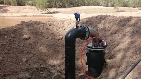
Solar false bore pump biggest on the East Coast
In North Queensland, an innovative farmer has teamed up with a group of suppliers to install the East Coast’s first...
-
Atlas Copco Compressors renews focus on quality service
Atlas Copco Compressors Australia has launched a renewed focus on compressed air, vacuum systems and on-site gas generation utility...
-
Marong receives new booster pump station
Marong, west of Bendigo, will receive a new 3ML concrete tank and booster pump station to improve water pressure...
-
Unrestricted pumping for WA irrigators
Western Australian irrigators in the Carnarvon region can now pump water from the Gascoyne River and Riverbed Sands after...
-
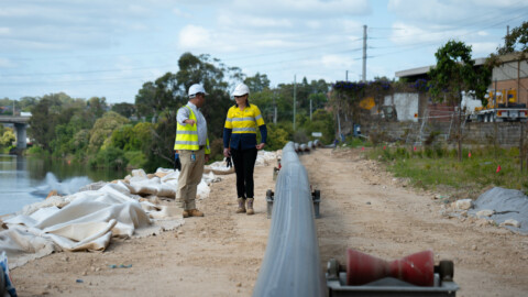
Liverpool Pump Station project hits new milestone
Sydney Water’s new Pump Station in Liverpool has hit a new milestone, with almost 700m of pipeline installed under...
-
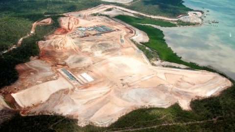
Australia Pacific LNG’s first LNG modules arrive in Gladstone
The Australia Pacific LNG Project has unloaded the first LNG modules on Curtis Island following their arrival into Gladstone...
-
Ichthys hook-up contract awarded
Samsung Heavy Industries (SHI) has awarded a contract for hook-up services on the Ichthys LNG Project (WA) Central Processing...
-
Analysis for Murray Darling Basin Plan
An independent social and economic analysis has been commissioned by the Victorian Government to understand how irrigators and communities...