


Large-scale and long duration energy storage will play a critical role in Australia to create a flexible and reliable energy system, support the increasing deployment of variable renewable energy sources, and to help manage the gradual retirement of conventional generation. There are a number of technologies that have been deployed to achieve this, with compressed air energy storage (CAES) one of the technologies looking to be established in the country to provide large-scale synchronous capacity. Here, we break down the technology and what equipment is involved, and explore the proposed 200MW utility-scale Advanced-Compressed Air Energy Storage (A-CAES) facility for Broken Hill, New South Wales.
What is CAES?
CAES is a method to store generated energy, allowing it to be used at a later time. At utility scale, this means that energy that is generated during off-peak (low demand) periods can be released at peak load (high demand) periods.
The technology is over 40 years old, and was seriously investigated in the 1970s for the nuclear power industry as a way to provide load to meet peak demand and following it, while also maintaining constant capacity factor.
Since then, it has become commercially available, offering potential for both small-scale, on-site energy storage, and large- scale installations to provide larger energy reserves for the electricity grid.
How does CAES work?
CAES plants have similar applications as pumped hydro storage, but instead of pumping water from a lower pond to an upper pond when there is surplus energy, ambient air or another gas is compressed and stored under pressure in an underground cavern (typically 500-800m deep) or container until it is needed at which point the pressurised air is heated and expanded in an expansion turbine to drive a generator to produce power.
Throughout the process, the air heats up during compression from atmospheric temperature to a storage pressure around 70-100 bar depending on the depth. Standard multistage air compressors using intercoolers and aftercoolers are needed to reduce the discharge temperature to 149/177°C and the cavern injection temperature down to 43/49°C.
This heat loss is then compensated for when the pressurised air is expanded in the turbine power generator phase by heating it in combustors using natural gas or by using the heat from a combustion gas turbine exhaust in a recuperator before the expansion cycle.
This process is known as the diabetic method. Alternatively, the heat from compression can also be thermally stored before entering the underground cavern to be used for adiabatic expansion where the heat from compression is retained and then reused during expansion. This is known as the adiabatic method.
Components of a CAES plant
The major components of a conventional CAES plant include:
• A motor/generator with clutches on both ends (to engage/ disengage it to/from the compressor train, the expander train, or both)
• Multistage air compressors with intercoolers to reduce the power requirements needed during the compression cycle, and with an aftercooler to reduce the storage volume requirements
• An expander train consisting of high- and low-pressure turboexpanders with combustors between stages
• Control system (to regulate and control the off-peak energy storage and peak power supply, to switch from the compressed air storage mode to the electric power generation mode, or to operate the plant as a synchronous condenser to regulate VARS on the grid)
• Auxiliary equipment (fuel storage and handling, cooling system, mechanical systems, electrical systems, heat exchangers)
• Underground or aboveground compressed air storage, including piping and fittings
Compressors and expanders are two components that play a key role in a CAES system. Compressors are designed or selected based on the application and designed storage pressure of the air.
Multistage reciprocating compressors are typically selected as the air pressure in a vehicle cylinder can reach 20MPa of storage pressure for higher energy storage density in a limited volume.
For a large-scale CEAS system, the pressure is about 8MPa, so multistage compressors are used and normally combined with axial flow compressors and centrifugal compressors.
Steam and gas turbines can be used for expansion. For example, a CAES plant in Huntorf, Germany, uses a steam turbine for first-stage expansion from 4.6MPa to 1.1MPa, and a gas turbine for second-level expansion from 1.1MPa to atmospheric pressure.
The selected thermodynamic cycle applied to a CAES plant can impact on plant costs, selection of components and overall operating/performance characteristics:
Conventional (diabatic) cycle
The conventional (diabatic) cycle consists of the intercooled compressor train, reheat expander train, motor/generator, control system, and the air storage along with auxiliary equipment (fuel storage and handling, heat exchangers, mechanical systems, and electrical systems).
In this cycle, the stored air is expanded through the reheat turboexpander train where it is heated (via combustion of fuel) sequentially in the high pressure and low pressure combustors before it enters the corresponding high pressure and low pressure expansion turbines.
Plants designed with this cycle are characterised by relatively high heat rate (approximately 5,500Btu/kWh) compared to more recent designs, and are best suited for peaking and spinning reserve duty applications. There are two major benefits of the conventional cycle.
The first is that it can generate three times the output for the natural gas input as the compression of the combustion air is separated from and independent of the gas turbine process.
This is because the compression stage typically uses about two thirds of the turbine capacity, and by separating this from the gas turbine process, the turbine has additional output.
This has environmental benefits as well, as the specific gas consumption is reduced and CO2 emissions can be abated by about 40-60 per cent depending on whether waste heat is used to increase the air temperature in a recuperator, with this providing around 55 per cent efficiency compared to power- to-power at around 42 per cent.

Source: Hydrostor.
Furthermore, as the air is not compressed using gas, lower cost excess energy can be used during off-peak periods. Plants utilising this method, use sing-shaft machines with the compressor-motor/generator-gas turbine both located on the same shaft and coupled via a gear box.
There are conceptual designs where the motor-compressor and generator-gas turbine will be mechanically coupled, making it possible to expand the plant modularly.
The main components of a conventional cycle plant are:
• Compressor train with intercooler and aftercooler
• Expander train
• Generator/motor
• A fuel/gas combustion system to preheat the released air
Recuperated cycle
The recuperated cycle is the conventional CAES thermal cycle with the addition of a recuperator which recovers the low pressure turbine waste heat to preheat the stored air before it goes to the high pressure combustor.
This allows a reduction of fuel consumption by about 25 per cent compared to a conventional cycle plant. This cycle was designed for primary operation as a source of peak power and as a load management storage plant. The main components of a recuperated cycle plant are:
• Compressor train with intercooler and aftercooler
• High and low pressure expansion turbines
• Generator/motor
• A fuel/gas combustion system to preheat the released air
• Recuperator
Combined cycle
The combined cycle includes the addition of a heat recovery steam generator (HRSG) and a steam turbine. The HRSG recovers the exhaust heat from the low pressure expander to produce steam, which is used to drive a steam turbine and provide extra power.
The additional power generated reaches full capacity around one hour after plant start up due to the thermodynamic inertia of the bottoming cycle equipment, therefore making this cycle appropriate for applications that need additional peak power for continuous long-term operations.
This cycle has a reduced specific storage volume per kWh produced than the conventional cycle. The main components of a combined cycle plant are:
• Compressors with intercooler and aftercooler
• Steam turbine
• Generator/motor
• A fuel/gas combustion system to preheat the released air
• Expansion turbine
• HRSG
• Boiler feed pump
• Condenser

Source: Hydrostor.
Steam injection cycle
The steam injection cycle is a conventional CAES cycle that has been adapted to use the HRSG to recover waste heat for steam production.
The steam is added to the airflow from the storage cavern to increase mass air flow through the expansion turbine, increasing the plant’s output power level. The mass of air to be stored per unit of power output is greatly reduced due to steam injection with the corresponding reduction of the storage volume and costs.
Like combined cycle plants, the additional power from the steam injection lags the power almost instantly produced by the air expansion turbine. The main components of a steam injection cycle plant are:
• Compressors with intercooler and aftercooler
• Turbines
• Generator/motor
• A fuel/gas combustion system to preheat the released air
• Expansion turbine
• HRSG
• Boiler feed pump
Compressed air storage with humidification
The compressed air storage with humidification (CASH) cycle involves the stored air being humidified in an air saturator before being injected into the combustion turbine.
Due to the humidification, the mass of air needed to be stored per unit of power output is reduced, therefore the storage cavern can be smaller than for other CAES cycle designs. The main components of a CASH cycle plant are:
• Compressors with intercooler and aftercooler
• Turbines
• Generator/motor
• A fuel/gas combustion system to preheat the released air
• Expansion turbine
• HRSG
• Boiler feed pump
Adiabatic cycle
Plants using the adiabatic cycle are still conceptual, with major experimental projects and commercial ventures so far failing to yield a viable prototype. The appeal of this type of CAES plant is that it has the potential to offer low-cost, large-scale operation without reliance on fossil fuels or rare materials.
This cycle can achieve higher efficiencies of up to 70 per cent by recovering the heat produced during compression and using it to reheat the compressed air during turbine operations. The main benefit of this is that gas is no longer needed to heat the decompressed air. The main components of the adiabatic cycle are:
• Compressors
• Expansion turbine
• Generator/motor
• TES system
Broken Hill Advanced Compressed Air Energy Storage (A-CAES) Project
While the Broken Hill A-CAES Project is not the first CAES plant to be proposed to be built in Australia, it is the first large- scale, long-duration energy storage project to be selected as a preferred solution in the first stage of a regulatory transmission planning process by a major utility, and if completed, it will be the first facility of its type in the country.
The Broken Hill Project is a proposed 200MW utility-scale A-CAES facility that is being jointly developed by Hydrostor and Energy Estate.

Basic functioning of a CAES facility. Source: Scientific American.
It will be located at a local decommissioned mine and is designed to provide up to eight hours of electricity discharge at a time (i.e. up to 1,600MWh). The feasibility stage development work for the project is supported with funding from the NSW Government’s Emerging Energy Program.
It will provide critical backup generation to ensure reliability of the electricity supply to the Broken Hill community and will solve significant congestion issues being experienced by existing renewable projects in the region.
The Broken Hill A-CAES project will allow the region to sustainably unlock the full economic potential of its traditional and renewable natural resources and our goals include working with existing and new resource companies to provide them with a low cost sustainable energy solution.
The facility will use off-peak or surplus electricity from the grid or a renewable source to run a compressor, producing heated compressed air.
Heat is extracted from the air stream and stored inside a proprietary thermal store, preserving the energy for later use. This adiabatic process will increase overall efficiency and eliminate the need for fossil fuels during operation. The compressed air will be stored in a decommissioned mine.
Hydrostatic pressure forces air to the surface where it is recombined with the stored heat and expanded through a turbine to generate. If the facility is approved for construction, Hydrostor will work with tier one OEM suppliers to deliver the equipment, including its turbomachinery and thermal management systems.
The above-ground facility will be constructed by best-in-class EPC firms, which have multi-decade experience delivering directly analogous systems on-time and on-budget, while the subsurface component is delivered by world-class cavern construction specialists, who deliver identical caverns for more rigorous applications.
Find Compressors Related Companies In The Pump Industry Capability Guide


-
Irrigation unlocking opportunities in Tasmania
Government investment in Tasmanian irrigation is creating economic growth and new job opportunities across the state. Reid Fruits at Jericho...
-
Odysseus mine works progress
Western Areas has released an update on the construction activities at its Odysseus mine, located at the Cosmos Operation,...
-
What sort of progressive cavity pumps are best suited to mining applications?
The pump industry relies on expertise from a large and varied range of specialists, from experts in particular pump...
-
Who is Regal Beloit?
Regal Beloit Corporation is a leading manufacturer of electric motors, mechanical and electrical motion controls and power generation products...
-
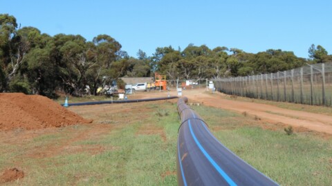
HDD marks milestone for Murraylands water network upgrade
SA Water has announced that more than half of the expected 7km of new water main has been laid...
-
Expression of Interest: main canal automation
Murrumbidgee Irrigation (NSW) is seeking expressions of interest for the automation of the Main Canal. The project scope covers...
-
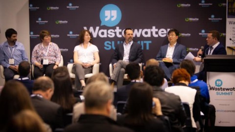
Wastewater Summit a feature of Waste Expo Australia
Ensuring the continued supply of safe drinking water is at the forefront of business operations for water organisations across...
-
WA pump station upgrades
The Water Corporation is set to begin work on a $10million wastewater upgrade in Western Australia, which includes pump...


