


by Ray Hardee, Chief Engineer, Engineered Software
This is a continuation of a series of articles on understanding the operation of fluid piping systems. We previously discussed how a piping system consists of three elements working together to achieve the system’s objectives.
The pump element adds energy to the fluid to overcome the static and dynamic head of the process elements in the system. These process elements, such as tanks, heat exchangers, strainers, pipelines, valves and fittings, require a certain amount of energy to deliver the fluid to make the products or provide the services at the desired production rate.
The third aspect of a piping system, the control element, also requires energy to regulate the key operating parameters of the process, which may include the fluid flow rate, pressure, temperature, pH, chemical content, or some other quality, safety, or environmental parameter.
Many think a control element as just an automatic control valve installed in the piping system. However, the control element includes all components in the process control loop, as well as the control scheme implemented to regulate the process parameter.
Let’s look at various aspects of the control element found in numerous industrial piping systems, including those in power plants, chemical manufacturing, water and wastewater, commercial heating and cooling, and other applications.
A typical piping system
Consider a typical application found in many facilities: a water collection system that takes wastewater from various locations throughout the plant and delivers it for further processing.
The system shown in Figure 1 consists of a sump that receives water from multiple floor drains, a wastewater collection tank, and all the interconnected piping.
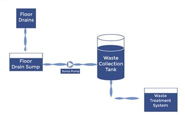
Figure 1: Wastewater collection system with no process controls.
The system must be designed and the flow rate controlled so as to not overflow either of the tanks during a variety of operating conditions from minimum to maximum flow of water from the drains.
Various process control options
There are various methods that can be used to keep the process under control and ensure neither tank overflows.
These methods may use instrumentation that measures the flow rates into and out of each vessel, pressure at different locations such as at the discharge of the pump, the levels in the tanks, or a combination of measurements.
In addition to what measurement to use, different control schemes can be implemented using that process parameter to ensure the system is operated safely.
Let’s use the tank level in the wastewater collection tank as the critical measurement and evaluate controlling the system using a bypass control scheme, and on-off control method, and an automatic control loop.
Bypass control
A simple method of controlling the wastewater collection tank level is using a bypass line as shown in Figure 2.
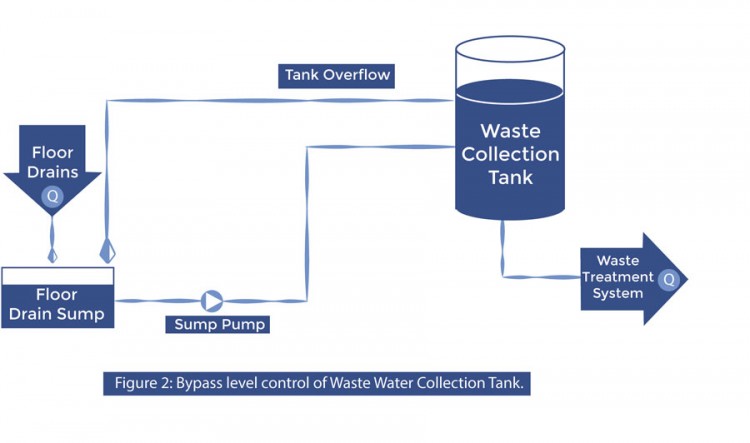
Figure 2: Bypass level control of wastewater collection tank.
The bypass consists of a pipeline running from the wastewater collection tank back to the floor drain sump or to some other location.
The penetration height of the bypass line establishes the maximum liquid level in the wastewater collection tank.
If the flow rate from the sump pump exceeds the flow rate out of the collection tank to the waste treatment system, the tank level will increase up to the penetration height of the bypass line, after which all excess flow will return back to the floor drain sump.
The advantage of this method is that it does not require any plant instrumentation or control valves, but the disadvantage is that there is a possibility of the floor drain sump overflowing.
Also, there is additional energy costs associated with pumping more water up to the wastewater collection tank than the downstream process can handle.
On/off control
On/off control uses high level and low level limit switches mounted in the waste collection tank that send a signal to a controller that can either actuate a block valve or start and stop the motor on the sump pump, as shown in Figure 3.

Figure 3: On/Off control of wastewater collection tank.
When the level rises up to the high limit, the controller can either turn the pump off or close the block valve. When the level drops to the low limit, the controller turns on the pump or opens the block valve. Using this type of control, the liquid level ranges between the high and low level set points.
There are some drawbacks to on/off control. The increased number of motor starts and stops increases the wear and tear not only on the motor, but also on the pump.
An additional cost for a soft starter on the motor may alleviate the expected increase in system maintenance.
If a block valve is used, the increased cycling of the valve can be expected to increase not only valve maintenance costs, but also overall system maintenance costs by subjecting the pump to continued operation at shut-off flow conditions.
Another disadvantage is that the level in the waste collection tank is not controlled to a constant value, but is allowed to fluctuate over a range of values.
This may be undesirable for the downstream processes.
Automatic level control
An automatic control loop consists of a primary element that measures a process parameter, a transmitter that sends the measured value to a controller, and a final control element that makes adjustments to maintain the process variable at the set point.
In the wastewater collection system shown in Figure 4, the primary element is a sensor that measures the collection tank level.

Figure 4: Automatic level control of wastewater tank.
The controller compares the signal from the level transmitter to a user entered set point and sends a signal to adjust the final control element if necessary.
The final control element can either be a control valve or a variable speed drive for the sump pump.
The advantage of an automatic control loop is the level will maintain a set value regardless of the flow rate coming into the floor drain sump and can be adjusted remotely.
However, there are additional capital and maintenance costs for the instrumentation, control valve, and variable speed drive.
If a control valve is used, there will be additional energy costs associated with the head loss across the valve, but if a variable speed drive is used, there will be lower energy costs when operated at lower system flow rates.
Summary
The pump, process, and control elements of a piping system all work together to meet the system design requirements.
The control element plays a critical role by regulating key production, quality, environmental, or safety parameters for the system.
There are several aspects to the control element that need to be evaluated, including which process parameter to measure and control, what instruments to use, what control method to implement, and how much variability is acceptable for the process.
These decisions will depend on the application and requirements of the system and the overall process.
The control element may also consume some of the fluid energy during operation, especially any control valve or flow meter that will have a pressure drop and head loss across it.
This energy must be added to the fluid by the pump and taken into account in the calculation of the pump’s total head.
Find Power Generation Related Companies In The Pump Industry Capability Guide


-
Altona Treatment Plant gets robotic cleaning
City West Water is employing a giant robot, which uses onboard pumps, to clean the Balance Tank (otherwise known...
-
The experience and capability of a world-leading pump manufacturer
Ebara is known worldwide as one of the largest and most diverse manufacturers of custom, industrial and general purpose pumps....
-
Flooding the forest
The Murray-Darling Basin Authority has brought together local companies to save the Hattah Kulkyne National Park. The area relies...
-
Hattah Lakes project wins engineering excellence award
Goulburn-Murray Water (GMW) was presented with the Engineering Excellence Award 2014 in the Environment category at the Victorian Engineering...
-
Engineering
A well engineered pump and system that is tailored to the application can dramatically improve the quality of service...
-
Tender: stormwater harvesting
Blacktown City Council, NSW is currently seeking tenders from suitably qualified contractors for the investigation, design, construction, installation, testing...
-
Pump efficiency number one issue for designers
A recent survey of pump design engineers at consulting and original equipment manufacturing companies has found that improving impeller...
-
ACCC takes legal action over “flushable” wipes
The Australian Competition and Consumer Commission (ACCC) is taking several companies to court for allegedly making false and misleading...


