

By Larry Bachus, The Pump Guy®
People know the water pump on the radiator of their car will run 18 to 20 years without problems. And, the compressor on their refrigerators will perform day and night for 20 to 25-years without leaking refrigerant gas or causing problems. They’re concerned that they can’t get similar life out of their circulating chill water and cooling tower pumps. Why are so many industrial pumps out of control?
The reason is simple. Too many industrial pumps are improperly mated into their system. The system is the pipes, elbows, valves, accessories and fittings leading to and away from the pump.
The piping system governs the pump. The centrifugal pump is the slave to the piping system. Therefore, the roots of most pump problems are planted in the system.
A pumping system has a flow requirement and a head requirement. Let’s consider ‘flow’ and ‘head’.
Flow is liquid volume per unit of time, like litres-per-minute (lpm), or cubic metres per hour (m3/hr.). Flow is production, a function of marketing and sales. Marketing people determine they can capture a percentage of sales of a certain consumer product (beer, petrol, tomato sauce, toothpaste, laundry detergent, or glue). The vice presidents of marketing, finance, and production meet and decide to manufacture the product.
The production engineer determines he can keep the store shelves filled if he makes the product at 2,500 litres per minute, or 150-m3/hr. So, the manufacturing operation requires a pump that delivers 150-m3/hr. This is flow. Flow is marketing and sales.
Head is energy. The units of energy are rated in ‘metres of head’. Head is the nature and design of the piping system. Head is the energy to transport a liquid, lift it, heat it, pressurize it, filter it, strain it, measure and package/bottle it with the piping system.
If moving a liquid through a piping a system consumes 12-metres of energy (head), then we need a pump that generates or overcomes 12-metres of resistance, at 150-m3/hr. of flow. We’ll want a pump with best efficiency coordinates at or close to 12-m @ 150-m3/hr. on the performance curve.
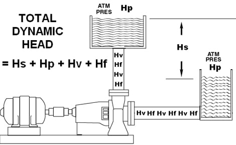
150-m3/hr. is rather easy to understand. The 12-m of system head requires some thought. The 12-m of system head is called the Total Head (TH). The purists use the term TDH, meaning Total Dynamic Head. Others say it means Total Developed Head.
The Total Head, or TDH is composed of four elements, added together:
1. The elevation differential, called the Static head or Hs.
2. The pressure differential, called the Pressure head or Hp.
3. The liquid velocity energy, or losses, called Velocity head or Hv.
4. The friction energy, or losses, called Friction head, Hf.
The Formula is simple:
TDH = Hs + Hp + Hv + Hf.
Let’s consider each of these elements:
Hs is static head. If you’re pumping from down here to up there, that elevation difference is the Hs in metres. Let’s say you are using a pump to elevate water in a cooling tower. The top of the cooling tower is 10-metres above the reservoir pan below the tower. The elevation change is 10-metres. The static head (Hs) = 10-m.
Here is another example:
Water collects in the bottom of almost all Australian mines. This water must be removed to prevent the mine from flooding. If the mine floor is a kilometre below the surface, we’d need a pump that develops at least 1,000 metres of static head to lift the water up to the surface, where the water might be released into a river or lake. By observing the system and noting the elevation change, this distance in metres is the Hs.
Pressure head, Hp, is also rather easy to understand. Hp is the pressure change across the system. If both the suction vessel, and the discharge vessel are exposed to the same pressure (whether high pressure, atmospheric pressure or vacuum) then there is no pressure differential, and no Hp to consider.
But, let’s say the suction vessel is closed, sealed and pressurized at 200-kPa. The discharge vessel is pressurized at 350-kPa. Now, there is a differential of 150-kPa of pressure across the system. The pump must generate additional energy, called pressure head (Hp) to overcome this pressure differential.
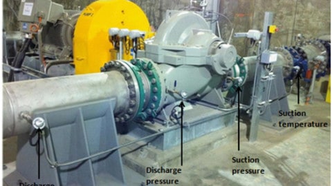
The calculation is: Hp = kPa differential x 0.102/ specific gravity. The 0.102 is the multiplier to convert kilopascals of pressure into ‘metres’ of head. The specific gravity of the liquid is the relative density or weight per volume. The pressure differential can usually be observed on the pressure gauges at the suction and discharge vessels.
Hv is velocity head. Creating and maintaining liquid velocity in the pipes also consumes additional energy that must be designed into the pump. Two tidbits of information are required. We need to know the velocity of the liquid (V) moving through the pipes in ‘metres-per-second’. And, we need to know the acceleration of gravity. The formula is simple. Hv = V2/ 2g, or velocity in m / sec. squared, divided by 2-times the acceleration of gravity (9.804-m. / sec. / sec.). Because the acceleration of gravity is a constant, then the Hv rises and falls with the liquid velocity.
Most design engineers will specify a pipe based on a liquid velocity of about 1.5 to 2-metres per second through the pipe. Slower is better unless there is an engineering reason for high liquid velocity in a pipe.
Finally, the friction losses, called Hf refer to the friction between the liquid and the internal surfaces of the pipes, valves and fittings. The friction in the pipes reduces or drags down the ability of the pump. The friction losses must be designed into the pump so that the pump will overcome the frictional losses of the system.
The mathematical formulas for Hf are:
For pipes: Hf = K x L/100 where K is a friction constant per 100-metres of pipe derived from pipe friction tables. L is the actual length of pipe in the system (in metres).
For valves and fittings: Hf = K x Hv, where K is a resistance constant derived from charts. Hv is the velocity head in metres, calculated earlier.
Notice that velocity (Hv) is a component of friction (Hf). Velocity head and Friction head work in concert and only exist when the liquid flows. Many people refer to Hv and Hf together as “resistance”. Just remember that resistance has two components.
Once again, TDH = Hs + Hp + Hv + Hf. Let’s consider a system where we must pump and raise ambient water at 200-m3 / hr. from one vented vessel or tank, up 11-m. into another vented vessel. The Hs is 11-m.
The suction and discharge tanks are vented at atmospheric pressure. There is no pressure differential and the Hp is zero. We will specify pipe diameter to that the water moves through the pipe at 1.6 m per second. The Hv computes to 0.26-m. The friction losses across the piping, valves, fittings and a strainer compute to 2.7-m. The Hf is 2.7-m.
We need a pump with a TDH of 13.96-m (11 + 0 + .26 + 2.7). We should select a pump with best efficiency coordinates as close as possible to 14-m of head @ 200-m3 / hr. of flow.
When comparing pumps for purchase, it is wise to purchase the most efficient pump for an application, even if the more efficient pump costs more to buy. Efficiency is tied to the monthly energy costs (cost per kW-hr.). Also, an efficient pump is usually a low ‘maintenance cost’ pump. We’ll talk about these in a future article.
Mating a pump to a system is really quite simple. When it is done correctly, the pump will run for a number of years without problems. Remember that I began this column citing your car’s radiator water pump and the compressor on your refrigerator.
The radiator water pump on your car has bearings and a mechanical seal on the shaft, the fridge compressor, too. The seal and bearings on your car’s water pump are not better than the precision mechanical seals and roller bearings you see every day on an industrial chemical process pump. Also, your car’s water pump and impeller are made from stamped parts. The parts are not precision- machined, balanced and aligned as you might expect on an industrial process pump.
So, you might ask, “How does the radiator water pump on my car (and
the compressor on my refrigerator) run for so many years without leaking, or failing or causing problems?” The fridge compressor and your car’s water pump give many years of trouble free service because these devices are properly mated into their systems.
As a pump consultant, I often go into plants whose pump maintenance costs have surpassed the maintenance budget. I see pumps that consume three and four sets of bearings and seals per year and spend too much time in the maintenance shop.
The reliability engineer perceives he has a bearing problem, or a vibration problem, or a maintenance problem. He tries to solve these problems with expensive gadgets with digital displays. Too often, the problematic pump is poorly mated into the system.
The vibrations, heat and high maintenance costs are not the problem. These are the manifestations of the real problem. Solve the real problem, and the manifestations will disappear.
We show how to mate new pumps, and replacement pumps into their piping systems in the Pump Guy lecture series. Maybe you can attend one of my upcoming lectures.
The Pump Guy is Larry Bachus, a maintenance practitioner, pump consultant, lecturer, and inventor. Larry is a member of ASME for 27-years. E-mail to: [email protected], phone 1-615-361-7295
Keep this article, or make a new file and store this article where you can find it quickly. This is your Cheat Sheet of useful pump information.


