


By Ray Hardee, Chief Engineer, Engineered Software
In the last article we gave a quick introduction to piping systems and the parts that are in every piping system. Every piping system is made up of three elements: the pump elements, the process elements and the control elements.
Each of these elements work together to meet the needs of the process system. If these elements work nicely together then the system will be trouble free, but if they don’t work well together chaos will ensue. For the next series of articles, we will look at each of the system elements in detail; we’ll start out by looking at the pump elements.
As previously mentioned, the pump elements include the pump, a drive adding energy to the pump, the pump seals and other supporting equipment. In this article we will focus on the pump and drive, specifically rotodynamic pumps driven by electrical motors.
The pump element supplies all the fluid energy to the system required by the process and the control elements. The pump drive takes power from an electric motor in which the electrical energy from the plant power grid is converted to mechanical power at the motor shaft.
The motor shaft is connected to the pump shaft where the mechanical power is used the move the impeller.
In a centrifugal pump, the process fluid in the pump suction is pulled into the rotating impeller. The rotating impeller causes the fluid to accelerate, converting some of the impeller’s mechanical energy into kinetic energy.
The accelerating fluid moves from the center and out to the tips; in looking at the cross sectional area between the impeller vanes you can see the cross sectional area increases and as such they convert some of the fluid’s kinetic energy into potential or pressure energy.
After making it to the tips of the impeller the fluid velocity is at its highest. In the volute area of the pump more of the fluid’s kinetic energy is converted potential energy causing a further increase in the fluid pressure. As you can see, the pressure is created within the pump’s impeller and the volute with typically two thirds of the pressure being developed in the impeller and the rest coming from in the volute.
What is so nice about a centrifugal pump is that it always operates as described on a pump curve. The pump curve provides a graph showing the pump head and efficiency as a function of the flow rate through the pump.
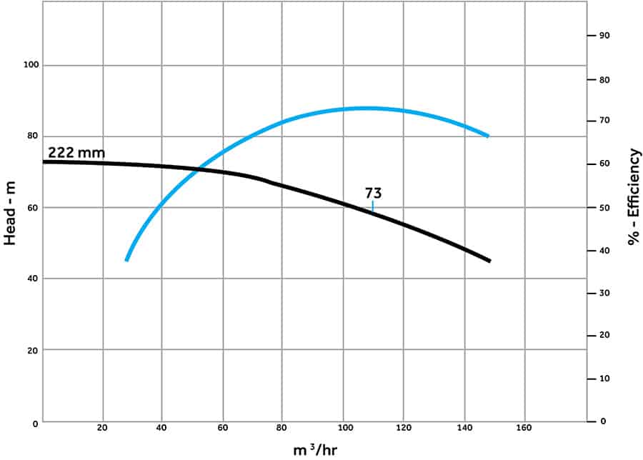
Figure 1. Example of a pump curve showing the head and efficiency as a function of the flow rate through the pump.
Figure 1 is an example of a typical pump curve; the data shown is for a 222mm diameter impeller taken at a rotational speed of 2950rpm.
The flow rate through the pump is entered on the x-axis, the head developed by the pump is shown on the left y-axis, and efficiency at which the pump converts the mechanical energy supplied by the pump shaft to the fluid energy is displayed on the right y-axis.
Looking at this curve, with a flow rate through the pump of 100m3 metres /hr, we can see the pump develops 61 of head and has an efficiency of 75 per cent.
What is so important about the pump curve is the pump will always operate on the pump curve. The pump curve can also provide a flow rate at a different value of head. Looking at the head axis on the pump we can see that at 50 metres of head the flow rate through the pump is 135m3/hr.
The pump head is not affected by the density of the process fluid. The pump curve is always tested with water at standard temperature and pressure as the test fluid.
If the density of the process fluid is 900 kg/m3 pump will still be as listed on the pump curve. Conversely if the process fluid has a density of 1,100kg/m3 the pump head will still follow the pump curve.
One final point, the pump’s performance is stated in fluid head but plant pressure gages read out in bars. As a result, to determine the pump head, you will need to convert from pressure units to metres of head.
This provides us with basics of the pump curve. In future articles we will see how the pump and process elements work together to determine the balance flow rate through the system. After that we will learn about how to adjust the flow of the system using control elements.
Find Engineering Related Companies In The Pump Industry Capability Guide


-
New developments with VSE units and SmartObserver
For many years, the octavis diagnostic amplifiers have been a mainstay in ifm efectors’ condition monitoring suite, and have...
-
Pump School: Pump Standards
There are many pump standards used in the pump industry today. These standards may be national, international, industry specific, company...
-
Engineers Australia announces new CEO
Engineers Australia has announced its new CEO who will be taking up the role on 3 October 2019. Dr...
-
FPT Industrial offers advanced engines for irrigation units
Within a highly comprehensive range, FPT Industrial offers a series of engines specifically designed for Industrial Power Unit (IPU)...
-
Variable speed drives in the dairy shed
Vacuum pumps are used to produce sufficient air flow to operate milk harvesting equipment and represent approximately 80 per cent...
-
Research into a new generation of ceramic pumps
Engineers from the Georgia Institute of Technology, Stanford, and Purdue University have developed a ceramic-based mechanical pump able to...
-
Selecting and applying positive displacement pumps (Part 3)
The PIA’s Australian Pump Technical Handbook is a cornerstone text for the Australian pump industry and, in our...
-
Intake design – part 2
The PIA’s Australian Pump Technical Handbook is a cornerstone text for the Australian pump industry and, in our opinion,...


