


By Ray Beebe, MCM Consultants and Federation University

Figure 1: Single pump to system
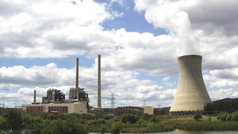
When a power station using large coal-fired boilers needed to increase a system flow, one solution put forward was to duplicate the outflow line. While this might be a good idea to meet a need, Ray Beebe shows that a simple duplication would have problems and puts forward an alternative solution.
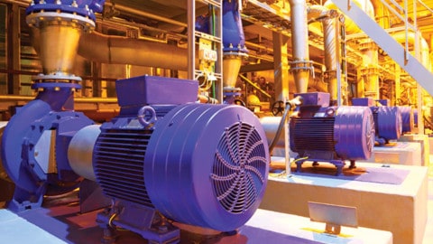
The power station of this story has large coal-fired boilers. During combustion, ash falls into the furnace hearth, along with ash deposits cleaned off much of the furnace waterwall area using water-sootblowers. Ash on the convection pass tubes and dust collected in the electrostatic precipitators joins the hearth ash to be sluiced by jets from a sluice pump into the ash sump. Two identical single-stage ash disposal pumps are installed, with one normally in service to pump the dirty water over two kilometres away to the disposal pond.

Figure 2: Pumps in parallel to the initial system
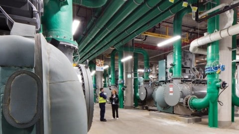
Every few months, the power station coal-fired boilers have to be washed off-line with water to fully clear the ash deposits from the furnace walls. The outside of the boiler is also washed. All the dirty water falls into the furnace hearth and overflows the ash sump, ending up over the floor, making not only a mess but proving hazardous to the workers.
The Maintenance Engineer proposed that both pumps be run together. When little change in flow was evident, it was proposed that the outflow pipeline be duplicated. Fortunately, before this measure was taken the performance aspects were checked.
Figure 1 sketches the Head-Power-Flow performance of one ash disposal pump operating to the initial system. Head-Flow tests had given the operating

Figure 3: Pumps in parallel to doubled system
point, and knowing the system Static Head of 20m, the system curve was found and superimposed on the pump curve, as shown. At the operating point, the pump flow was 120L/s at a head of 84m, with power of 115kW drawn. The motor rating of 132kW allowed a sufficient margin for normal operation.
When the curve for both pumps operating in parallel is drawn, as shown in Figure 2, the operating point shows that about 130L/s flow would be achieved – very little extra due to the relative steepness of the system curve and the flatness of the pump Head-Flow curve.
If the pipeline was duplicated, the combined system curve would be flatter, as shown in Figure 3. The total flow with both pumps running would be doubled to 240L/s, with each pump providing the same flow as before.

Figure 4: One pump alone to doubled system
However, when starting up the system, there would be a problem. If one pump was started with both systems open to flow, the power drawn would exceed the rating of the motor and it would trip on overload protection: see Figure 4.
The solution: with one system only open to service, start one pump, then the second one. Only then, open up the second system to obtain the desired increased flow.
However, the system as designed had no isolating valves, so to enable the solution a suitable valve would need to be installed in the new line. After due consideration, the system was left unchanged.
Find Power Generation Related Companies In The Pump Industry Capability Guide

-
What is a peristaltic pump and what are the benefits?
Principles of operation The term peristaltic pump is applied to various ranges known as hose or tube pumps. Although...
-
Considerations when selecting and installing a progressive cavity pump
What do you feel are the most important considerations when selecting and installing a progressive cavity pump? Question answered...
-
Custom-built progressive cavity pumps for oil and gas applications
The pump industry relies on expertise from a large and varied range of specialists, from experts in particular pump...
-
FPT Industrial powers your business, no matter the location
Whether you are operating in the alps or in a remote rural location, you can depend on FPT Industrial...
-
Tender: power station offsite overhaul of pumps
Deltra Electricity has issued a tender for the offsite overhaul of electric feed pump main pump cartridges and booster...
-
Barangaroo South takes building services underground
Located on the western edge of the Sydney CBD, Barangaroo is the largest urban renewal project to take place...
-
State of the Industry in 2018: increasing opportunities bring a rise in competition
The fifth annual Pump Industry State of the Industry survey conducted recently showed a positive shift in expectations for...
-
Pumped hydro potential for Tasmania’s West Coast
Tribute Power Station on Tasmania’s West Coast is being considered as a potential site for the installation of pumped...


