


In this edition of “pump school” we look at the principles of operation for air-operated diaphragm pumps.
Basic design features
Most diaphragm pumps (in this example we are using Sandpiper) are driven by compressed air. The directional air distribution valve and pilot valve, referred to as the “air end”, are located in the centre section of the pump. Liquid moves through two manifolds and outer chambers of the pump, referred to as the “wet end”. Generally, check valves are located at the top and bottom of each outer chamber or on a common manifold. The two outer chambers are connected by suction and discharge manifolds. The pumps are self-priming.
No-lube air distribution valve
During operation, the air distribution valve controls alternate pressurising of one diaphragm, then the other. The valve automatically transfers air pressure to the opposite chamber after each stroke. This provides alternating suction and discharge strokes, as the diaphragms move in parallel paths. Sandpiper air valves require no lubrication. This is the preferred mode of operation as clean, dry air will enhance pump performance.
Diaphragms
Flexible diaphragms are clamped at their outer perimeters, between the inner and outer chambers. The diaphragms are connected at their movable centres by a rod.
Check valves
As fluid moves through the pump, check valves open and close. This allows each outer chamber to alternately fill and discharge. The check valves respond to differential pressures. Ball-type check valves can pass small particles.

The pumping cycle
As the air distribution valve directs pressurised air to the left diaphragm, the diaphragm is pushed outward. This is a discharge stroke, which forces liquid from the left outer chamber. Discharged liquid moves from the chamber, through an open discharge check valve, and exits the pump at the discharge manifold.
The position of the discharge port can be top, bottom or side. As the left diaphragm is pressurised outward, the connecting rod pulls the right diaphragm inward on a suction stroke, which fills the right chamber with fluid. Liquid enters the pump at the suction manifold, moves through an open suction check valve and fills the chamber. At the end of the cycle, the air distribution valve automatically shifts the air pressure to the opposite diaphragm, initiating another pumping cycle.
Article courtesy of Kelair Pumps Australia “When Pump Knowledge Matters”
Phone: 1300 789 466 or visit www.kelairpumps.com.au
Find Valves Related Companies In The Pump Industry Capability Guide


-
Tender: sports field irrigation and drainage
Blacktown City Council (NSW) requires experienced contractors in sports field irrigation works and drainage works for three separate packages...
-
Marketing 101 for pump companies: how to get your business noticed
With hundreds of local and international businesses vying for a customer’s attention, pump companies need to know how they...
-
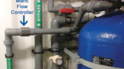
Accurate and cost-effective flow control
Many water treatment processes require an accurate and inexpensive method of controlling flow rate. The Maric Flow Control Valve...
-
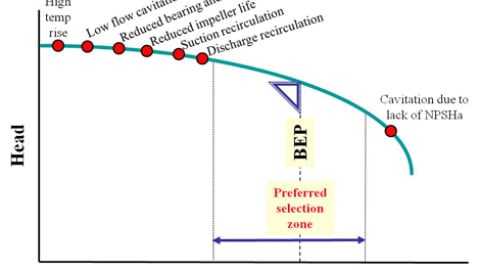
Understanding pump curves #5 : Minimum flow – part one
Ron Astall, United Pumps Australia Ask ten different pump engineers for their guidelines on establishing centrifugal pump minimum flow...
-
What is a check valve and how does it work?
Check valves are found in almost every industrial application, acting as non-return or one-way valves. Generally simple devices, check...
-
What is a lobe pump and how does it work?
Pump overview: Lobe pumps are found across a variety of industries, specifically those where hygiene and sanitisation are crucial...
-
Let’s get classy: pump classification
Readers and PIA members will no doubt be familiar with the Australian Pump Technical Handbook, the book first published...
-
Pump school: How does viscosity affect centrifugal pump performance?
Question: How does viscosity affect centrifugal pump performance? Answer: Pump users are sometimes confronted with the problem of applying...


