
by Arun Karuppasamy
In this paper we discuss a case study where a multistage barrel type centrifugal pump was re-staged several times to accommodate changing flow and pressure conditions. The re-stagings were carried out with the prime objective of accommodating decrease in flow and head requirements and were accompanied by frequent mechanical seal failures. We discuss the probable causes in detail and the short/long term solution options to address the issue of changing operating conditions and improving uptime.
Centrifugal pumps are volume flow dependent machines designed for a rated point and optimised for good performance over a range of operating conditions (flow and head requirements). There is however a limit to the range where the pumps perform optimally. Operation beyond this range not only results in sub-optimal performance, but also results in mechanical issues such as vibration, temperature rise, high wear and tear, etc. In extreme scenarios it may even lead to trips and failure of the mechanical parts.
The operating conditions of flow and head are not constant for a declining field where the rate of production is declining. The rate of decline may differ depending on the field type, characteristics and operating philosophy. Taking into account the need to design the centrifugal pumps to cater for the changing operating conditions, pumps are designed such that they can be re-staged to maintain optimum performance. Re-staging of pumps can be achieved either by changing the diameter of the impellers or, depending on the requirements, by addition or removal of impeller stages.
In the case of mature oil fields the current production rates may be just a fraction of the original design. The change in operating conditions for a pump may be sufficiently different from the original design conditions such that even re-staging of pumps does not alleviate the operating issues of high recycle flows and throttle operations. This can lead to energy wastage and high operational expenditure cost due to mechanical failures and frequent trips leading to loss of production.
Re-staging to some extent can address the issue of declining production however there are limitations. Re-staging is similar to a new design selection, and therefore requires due diligence and consideration. If standard design procedures and validations are not carried out during re-staging, then this may become the potential source for serious operating issues.
Case study
The pump under consideration is a multistage barrel type Main Oil Line (MOL) condensate pump on an offshore platform. The MOL pump is backed by a Booster pump to provide a safe NPSH margin. Each pump has its own recycle line to ensure that the pumps always operate at a safe minimum flow. The recycle flow from the Booster is routed to the LP separator while the MOL recycle feeds back, via the cooler, to the MOL pump suction. A schematic of the flow diagram is shown in Figure 1.
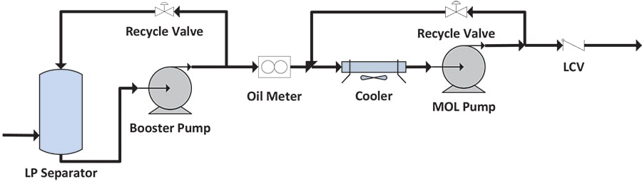
Figure 1. Booster and MOL pump system schematic
Problem definition
The MOL pump systems were greatly oversized for its current operating duty and experienced frequent mechanical seal failures and trips due to a high level of vibration. Frequent shutdowns due to seal failures and trips were consequently affecting the production. A study was initiated to review the pump and seal design to find the root cause of the problem and recommend modifications. The key objectives of the study were to provide a short term solution to improve uptime and availability and long term recommendations for possible future tie-back requiring increased head capacity.
MOL pump design and re-staging summary
The MOL pump is a heavy duty, barrel type, multistage fixed speed design with a maximum impeller capacity of six impellers of maximum diameter of 460 mm. The pumps were initially installed with five impeller stages of 430 mm diameter. Later in time, due to changing operating conditions with new tie-backs the pumps were uprated to six stages (4x 430 mm and 2 x 400 mm).
Recently due to field depletion, both flow and pressures have reduced. The pumps were largely oversized for its matching duty hence it was de-staged to four impeller stages of diameter 430 mm. The schematic of the pump internals for the initial design and the re-staging summary is shown in the Figures 2 – 4.

Figure 2. (top) Figure 3. (middle) Figure 4. (bottom)
Source of instability
Review of the operating data and maintenance history showed that the seal failures and trips due to vibration started sometime after the first re-staging, however the frequency of seal failure and trips were significantly higher after the second re-staging. The marked difference between the operating conditions and pump configuration from the first and second re-staging was that the flows were significantly lower after the second re-staging, and the number of impeller stages were two less compared to design capacity.
A detailed pump design and seal failure report review was carried out as a part of the root cause analysis to find the source of instability which resulted in the mechanical seal failures and frequent trips.
Pump design review
High recycle rates – shift in minimum continuous stable flow
During the operations review it was observed that the MOL pump recycle rates were circa 80{87a03eb4327cd2ba79570dbcca4066c6d479b8f7279bafdb318e7183d82771cf} of the net flow, which was 30{87a03eb4327cd2ba79570dbcca4066c6d479b8f7279bafdb318e7183d82771cf} more than the original design Mean Continuous Stable Flow (MCSF). MCSF is a minimum flow limit; operations at flows lower than this limit would result in high vibration. The design MCSF, which is a function of many parameters initially based on the original design, had changed considerably after the two re-staging activities. Any attempts to operate at flows close to original design MCSF resulted in high vibrations. Hence historically the pumps operated with high recycle rates to keep the vibration to a minimum.
High recirculation flows either at the suction end or the discharge end of the impellers were the cause for the vibration at reduced flows. Depending on the ratio of inlet to outlet diameter, either suction or discharge recirculation is predominant. It is important to note that for multistage pumps, discharge recirculation occurs at a higher flow rates compared to the suction recirculation. A typical pump characteristic with flow instabilities is shown in Figure 5.
During the second re-staging the five impeller wheel configuration was de-staged to four wheels and the impeller diameters were increased by circa 7{87a03eb4327cd2ba79570dbcca4066c6d479b8f7279bafdb318e7183d82771cf} (for the impellers stages 1, 3 & 6). The increase in diameter sometimes affects the discharge recirculation limit. Through theoretical calculations it was established that the second re-staging has resulted in a shift in the MCSF flow towards the high flow discharge recirculation flow rates. This shift in the minimum flow limit is illustrated in Figure 6. From the design review it was found that the cause for high vibrations at flows closer to the original design MCSF was due to the shift in the minimum flow limit.
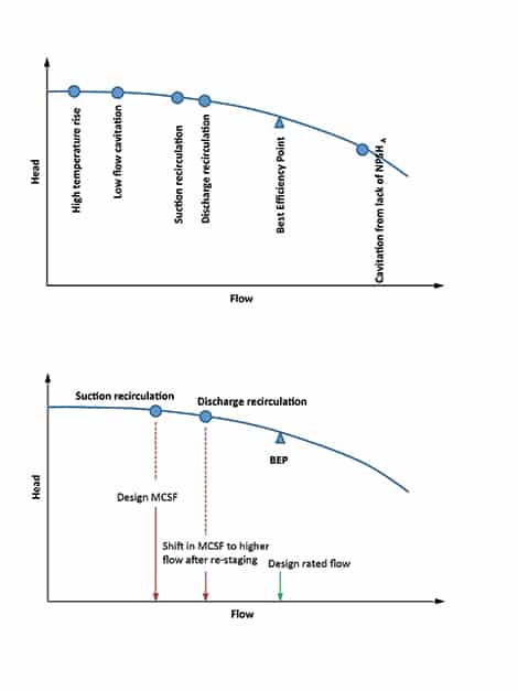
Figure 5 (above). Centrifugal pump general characteristics
Figure 6 (below). Effect of recirculation on minimum continuous stable flow
Effect of high recycle rates
The pumps have recycle lines to ensure that they always operate at a safe minimum flow. It is normal design practise to route the recycle flow back to the suction separator, which itself acts as buffer that eliminates the pulsation of the recycle flow which can affect the pump suction flow. In the case of the MOL pump, the recycle flow from this pump is fed back via the cooler to the MOL pump suction as shown in the pump system schematic in Figure 1.
In the absence of any mechanism to buffer the pulsation, this resulted in a cascading effect amplifying the disturbance introduced in the pump suction end in a cyclical manner. This introduction of highly unstable pulsating recycle flow at the suction of a high energy, heavy duty pump was the major source of destabilising excitation to the pump.
In addition to this, the de-staging from six to four stages also resulted in some residual axial thrust imbalance, as confirmed by the rotor-dynamics study report by the Vendor. The pulsating flow introduced by the high recycle rates coupled with the axial thrust imbalance resulted in axial movements affecting the mechanical and labyrinth seals.
Seal design review
The seal system consists of a double mechanical seal cartridge supplied with barrier fluid type ISO VG 10 at the drive and non-drive end. The seal faces are of tungsten carbide (rotating part) and carbon (static part) material. The seal oil pressure is maintained within the normal operational limits.
The seal vendor carried out detailed seal failure analysis after each failure. The failure analysis reports showed clear evidence of axial movement and pitting on the rotating seal face, as well as chipping on the carbon stationary seal faces which is common when seal barrier fluid becomes contaminated with process fluid.
In the design review it had been established that the high rate of pulsating recycle flow coupled with the axial thrust imbalance could have resulted in axial movement. This was confirmed by seal failure analysis. Further to this, continuous fluctuation of the inlet oil pressure at the suction could have set the rotor in a shuttling mode. Fluctuations (peak-to-peak) of similar magnitude to the inlet pressure mean value were also expected. If the pressure peaks were higher than the barrier fluid pressure, contamination would occur, which would also result in the loss of dynamic sealing leading to leakage and failure.
Summary of pump design and seal failure review
The MOL pumps were forced to operate at high rates of recycle due to the shift in the MCSF as a result of re-staging. The high rates of pulsating recycle flows coupled with the axial thrust imbalance introduced due the de-staging resulted in axial movements. These axial movements and the inlet pressure pulsations resulted in the contamination of the barrier fluid resulting in the frequent mechanical seal failures.
Short-term solution
There were two sources for the possible cause of excitation of the destabilising forces; firstly the high rates of pulsating recycle flow, and secondly the axial thrust imbalance. The simple cost effective solution involved re-routing the MOL recycle flows to the booster pump separator, however this was not viable due to the location of the inter-stage oil meter; moving this meter to the MOL pump discharge would have been both complex and costly.
The practical solution was to reduce the recycle flow rates, this could be achieved by re-staging with the most appropriate impeller selection such that the MCSF could be reduced and at the same time re-introduce positive axial thrust balance.
The recommendation was to re-stage the original hydraulic design impellers to six impeller stages of reduced diameter. The Vendor carried out a design review and high level rotordynamics study to validate the proposed design and confirmed that the new re-staging would in fact reduce the recycle rates significantly and also introduce positive thrust balance.
Long-term solution
The key requirement of the long-term solution was a recommendation for a possible future tie-back that would require increased head capacity. With the existing pump design, it was not possible to achieve the required head by re-staging, and further, the expected flows were just a fraction of the current flows. The best solution identified was to install new pumps with an option to initially operate in 2×50 {87a03eb4327cd2ba79570dbcca4066c6d479b8f7279bafdb318e7183d82771cf} mode, switching to 1×100 {87a03eb4327cd2ba79570dbcca4066c6d479b8f7279bafdb318e7183d82771cf} at reduced flow later in life.
Arun Karuppasamy is a Rotating Machinery Consultant at g3baxi partnership, UK. He has experience in the design and development of turbomachinery specialising in compressors, pumps and gas turbines for upstream oil and gas business. He holds a Masters Degree in Aeronautical Engineering from Indian Institute of Technology, Kanpur.
Find Related Companies In The Pump Industry Capability Guide


-
Manual pumps enlisted after lightning strike damages reservoir
Armidale Regional Council in NSW is running pumps manually during the day to partially restore water pressure to homes...
-
APPEA makes RET review submission
Oil and gas industry body APPEA has made a submission to the Renewable Energy Target (RET) Review Expert Panel...
-
Kurnell Refinery conversion successfully completed
The decommissioning, demolition and conversion of the Caltex Kurnell Refinery in NSW into Australia’s largest fuel import terminal has...
-
$20 million Atlas Gas Pipeline contract awarded
The contract for the construction of the 60km Atlas Gas Pipeline has been awarded, with the first gas expected...
-
Industry calls for federal funding for gas supply
Oil and gas industry representatives from Australian Energy Producers (AEP) have called on the Federal Government to allocate new...
-
Two new offshore greenhouse gas storage areas announced
The Federal Government has approved two new offshore greenhouse gas storage areas in an effort to provide Australia with...
-
New bioenergy recycling facility for Western Sydney
Sydney Water has announced the construction of its first food waste to bioenergy recycling facility situated in Western Sydney,...
-
Western Surat Gas Project wells go online
The first 30 appraisal wells have been brought online as part of Senex Energy’s phase two investment program on...