


By Ray Hardee, Chief Engineer, Engineered Software
Choosing the size of a pump discharge pipe can be a complicated process, with a range of factors to consider. Ray Hardee shares his insights into how choosing the right size discharge pipe can reduce operating time and costs.
I was teaching a Piping System Fundamentals course at an open pit copper mine and mill in the southwestern United States.
During my introduction I stressed the importance of understanding how the individual items of a piping system work together. I then went around the room asking each attendee what they did at the facility and what they hoped to get out of the course.
Each attendee had a specific topic of interest and I remember the dewatering engineer saying his goal was to improve the operation of the dewatering pumps.
Being that the mine was in the desert, I asked him how big the pumps were. He mentioned they were mounted on a semitrailer so they could be moved around the mine, along with a second semi for the diesel electric power supply.
Even though they were in the desert, all the rainfall would run off the ground resulting in flash floods that could quickly collect in the mine causing a disruption in production.
During the course of the training, when I discussed system static head, I made a point that the static head of the dewatering system amounted to the difference in elevation between the water level at the bottom of the mine, to the elevation of the end of the discharge piping.
When we covered the material on pipeline sizing, the dewatering engineer asked why we needed to perform this calculation.
He said his rule of thumb was to size the discharge pipe to that of the pump’s discharge flange.
For example, if the pump’s discharge nozzle was 150mm, he would use a 150mm nominal size pipe for his discharge header. In this article we’ll discuss why his rule of thumb may be costly.
The system
A piping system is made of three elements: the pump elements, adding all the fluid energy; the process elements, making the product or providing the service; and the control elements, improving the product quality. Figure 1 shows the system details.

Figure 1. Layout of the example piping system showing the pump and process elements. Control of the system is achieved by turning the pump off when not required.
In this example system the pump is an end suction design with a manufacturer’s identifier of 8×611, operating at 3,000rpm.
The pump curve used in this example can be found in Figure 2. Based on the manufacturer’s information, the pump suction flange is eight inches in diameter (200mm) and the pump discharge flange is six inches in diameter (150mm), with the eleven inch (279mm) indicating the pump’s maximum impeller diameter.
The process elements consist of the supply tank, with a liquid level of zero metres above the common datum.
The destination tank has a liquid level of 62m above the common datum. A short 350mm diameter pipeline serves as the pump’s suction line with insignificant head loss.
The discharge pipe is 1,200m in length made of steel schedule 40 pipe. We will vary the pipe diameter to demonstrate how a change in the pipe diameter affects the flow rate through the system.
Finally, the control elements of the system consist simply of an on/off control for the pump. When the supply tank is pumped down, the pump shuts down to prevent the pump from running dry; when the supply tank is full the pump is turned on.
As a result, all the energy supplied by the pump is used to move the fluid through the process elements. Now that we have the three elements defined, let’s see how a change in the pipe diameter effects the flow rate through the system.
Looking at the system
First we will look at the system with a 150mm nominal size discharge pipe. This is the same diameter as the discharge flange on our pump. The resulting flow rate through the system is 171.9m3 41.97m of fluid in the discharge pipeline. Adding the head loss of the pipeline with the system’s static head of
62m results in a head of 103.97m for the process and control. To check this result, we can see from the pump curve that a flow rate of 171.9m3 rate through the system is such that the head produced by the pump is equal to the head consumed by the process and control elements.
Next we’ll calculate the power cost needed to pump 1,000m3 of water at 15°C through a 150mm pipe using Formula 1.
 Where:
H = pump head in metres of fluid
ρ = fluid density in kg/m3 (999)
ηM = motor efficiency (.94)
ηP = pump efficiency (.48)
$/kWh = power cost per kWh (.20)

Table 1. How the system operates with various pipe diameters, along with the resulting cost in Australian dollars per 1,000m3 pumped.
From the table, you can see interaction between the various elements found in a fluid piping system. As you can see, as the pipe diameter increases, the head loss in the pipeline decreases along with the fluid velocity.
With lower pipeline head loss in the larger pipe diameter, more of the pump’s energy can be used to move the fluid.
As the flow rate increases in the pump, the head produced by the pump decreases as demonstrated on the pump curve (Figure 2). We also notice changing the flow rate through the pump varies the pump efficiency.

Figure 2. Manufacturer’s supplied pump curve for pump used in the example system.
Graph 1 shows how changing the nominal pipe diameter affects the pumping costs. As you can see from this graph, sizing the discharge pipeline to match the pumps discharge flange is not the most economical choice.
The other item to point out is that the pumping cost per 1,000gpm decreases rapidly but the savings decrease with increasing pipe diameters.
Increasing the pipe diameter increases the construction cost of the pipeline. As a result, accurately optimising the system would require the calculation of both the construction costs and operating cost for each available nominal pipe size.
This can become a tedious calculation and is best performed by specialised computer software.
Pipeline sizing parameters
Rather than performing a detailed cost optimisation for sizing pipelines, companies have developed piping specifications based on the process fluid being handled.
These specifications have been developed over time, based upon the company’s needs and experiences.
A chemical process plant will typically have many pipe specifications to handle the various process fluid they have, where an industrial plant may have a few specifications for the cooling fluids and transporting fluids needed for the process.
The Crane Technical Paper 410, Flow of Fluids Through Valves, Fittings, and Pipe, provides recommended fluid velocities for general service applications, pump suctions, and municipal applications.

Graph 1. The pumping cost per 1,000m3 for pumped fluid for various nominal pipe diameters.
The pipe fluid velocity range for general service applications is between 1.2 to 3m/s.
How do pump manufacturers arrive at a flange diameter?
After all this, you may ask why the pump manufacture doesn’t size the pump discharge flange for the recommended pipe diameter. There are a variety of reasons for this:
- The distance the fluid travels from the impeller tips to the discharge flange is short compared to the discharge piping. As a result, higher fluid velocities within the pump can be used because of the limited head loss due to the moving fluid and the stationary pump.
- The larger the discharge flange, the greater the pump footprint. Since one of the major costs of the pump is the pump case, a larger flange size would increase the size and cost of the pump.
- To minimise the number of castings required to meet their customers’ pumping needs, a manufacturer may trim the impeller, or design the pump to operate at various synchronous speeds. For example, the manufacturer supplying the pump in the system makes it available with impellers ranging from 229279mm. In addition, the pump is available with both 1,500 and 1,000rpm drives. The variation in the pump impeller diameter and synchronous speed affect the flow rate through the pump.
Conclusion
As shown in this article, it is not the recommended practice to choose the pump discharge pipe based on the pump discharge flange size.
As we saw in this application, sizing the pipe diameter to match pump discharge diameter resulted in a greater unit cost for pumping the process fluid.
In addition, for this system, the smaller pipe diameter resulted in lower flow rates through the system.
As a result, by sizing the pipeline correctly, you can reduce not only your operating costs but also the time the pump needs to operate. In our mine dewatering example this would pump the mine out faster allowing the mine operation to return to normal quicker.
Find Engineering Related Companies In The Pump Industry Capability Guide


-
Revitalising a heritage listed pump station
The City of Perth is seeking expressions of interest regarding the revitalisation and reuse of the heritage listed Hill...
-
New pump training centre
Hydro Innovations recently opened a new training centre, called the Hydro Innovations Pump Institute, to assist its customers in...
-
Ingham water plant pump upgrades completed
The upgraded Ingham Deport Water Treatment Plant has been officially opened as part of National Water Week, with the...
-
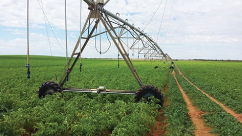
Irrigation innovation: putting water back in the Murray
Record levels of government funding are providing local growers along South Australia’s River Murray with the opportunity to remain at...
-
Ichthys project receives mooring installation
Mooring installation works have begun at the Ichthys Field in the Browse Basin (WA) as part of the INPEX-operated...
-
TasWater’s Pioneer project nearing completion
TasWater has replaced Pioneer’s reticulation network, bringing the treated drinking water supply pipeline closer to completion. The existing TasWater-owned...
-
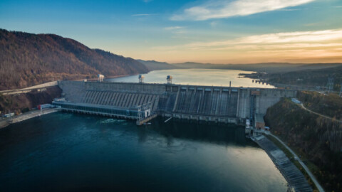
Construction to begin on $777 million Kidston pumped hydro
Construction is to commence on the $777 million Kidston Stage 2 pumped hydro energy storage (PHES) project – following...
-
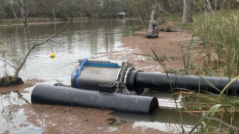
New pump screens to benefit VIC farmers and wildlife
The North Central Catchment Management Authority (CMA), Victoria, is trialling two new pump screen designs and is keen to...


