


Snowy 2.0 is a major pumped-hydro expansion of the existing Snowy Mountains Hydroelectric Scheme, operated by Snowy Hydro Limited.
Construction of the original scheme started in 1949 and was completed in 1974. It now comprises nine power stations, housing 33 turbines with a total generating capacity of 4,100MW, one pumping station, one pumped storage facility, 16 major reservoirs, 145km of interconnected tunnels and 80km of aqueducts.
The new Snowy 2.0 project will utilise the scheme’s existing Tantangara and Talbingo reservoirs (with a gross head differential of over 700m for power generation) by constructing 27km of connecting power waterway and an underground power station.
Snowy 2.0 will add 2,000MW of energy generation capacity and, with the capacity to generate power for seven days without recharge pumping, it will provide 350,000MWh of energy storage to Australia’s energy supply reserves.
As aging thermal power stations are being retired and the share of renewable energy sources such as solar and wind power is increasing in the energy market, the Snowy 2.0 pumped storage project is pivotal to Australia’s economy and energy transition, to balance the intermittent availability of wind and solar power with large-scale energy storage.
Together, renewable energy resources and Snowy 2.0 will contribute to the stability of Australia’s energy system as it moves into a low-emissions future.
Project history
Plans to construct a hydropower station between the Tantangara and Talbingo reservoirs were first considered in 1966, with subsequent studies undertaken in 1980 and 1990.
Initially, a scheme of 500MW capacity was investigated, which was increased in the 1990 study to 1,000MW. By 2017, due to the forward energy outlook, the increase in renewables within the National Electricity Market (NEM) and the need for huge amounts of storage in the future, a project capacity of 2,000MW was adopted.
A feasibility study carried out in 2017 showed that the Snowy 2.0 scheme was technically and financially feasible, and a Reference Design was prepared by Snowy Hydro.
From early on, contractor participation, both civil and electrical-mechanical, was encouraged to take advantage of their knowledge in technology advances and their expertise in underground construction technologies to develop the most efficient, reliable, economic and safe pumped storage project possible.
Following a rigorous tendering and bid evaluation process, a Final Investment Decision was reached in December 2018 and an Engineer, Procure and Construct contract was awarded to Future Generation, a joint venture between Salini Impregilo, Clough and Lane as the principal contractor, and Voith Hydro for the electrical-mechanical work, as subcontractor to Future Generation.
Construction onsite has commenced and first power is expected to be delivered to the grid by late 2024/early 2025.
To build Snowy 2.0, a temporary village will be created to house a workforce of approximately 2,000, which will become the third largest town in the area. The project will provide employment opportunities for thousands of indirect workers.
Project Details
General arrangement
Most of the Snowy 2.0 scheme will be located underground and will consist of large water intake structures up to 90m in height, located on the banks at Tantangara and Talbingo reservoirs, a single headrace tunnel of 9.9m internal diameter, approximately 17km long, crossing under the Great Dividing Range in an east-west direction.
At the end of the headrace tunnel, a 250m-high, 25m-diameter surge shaft will be located. Downstream of the surge tank, the headrace tunnel will feed a single 1.6km-long, 25 degrees-from-horizontal inclined pressure shaft, followed by a manifold at its base and three penstock tunnels which will subsequently bifurcate to feed six single pump-turbine units in the machine hall of the power station.
The draft tube tunnels on the downstream side of the machine hall will merge into three collector tunnels, which will meet at the bottom of the approximately 200m-high tailrace surge tank.
Downstream of the tailrace surge tank, the waterway will continue as a single 9.9m diameter tailrace tunnel for approximately 6km to the Talbingo intake structure.
The power station complex will be located approximately 700m underground, with a maximum depth of rock cover over the power waterway of up to 800m.
In addition to the power waterway, approximately 11.5km of access tunnels and construction adits will be required for the construction and operation of the underground power station.
This will include the main access tunnel as the primary access into the power station and the emergency egress, cable and ventilation tunnel, both approximately 2.5km-long.
High voltage power lines currently exist in the area, however, additional transmission lines and a substation are planned to be constructed and Snowy 2.0 will connect into these.
A longitudinal section of the power waterway and a cross section of the power station complex are shown on Figure 1 and 2, respectively (see Pump Industry Summer 2020, pages 66-67 for Figures).
Electrical and mechanical features
The installed capacity of Snowy 2.0 will be 2,000MW in both generating mode and pumping mode. Six, 340MW, single-stage, reversible pump-turbines will be installed, of which three units will be conventional synchronous machines, and three units will be variable speed (asynchronous).
The six pump-turbines are based on a Francis-type machine, which, due to the high head of up to 730m and large power output of up to 374MW (dynamic capability), are considered to be on the limits of suitability for this type of hydraulic machine.
Despite this, reversible Francis machines are considered to be the most appropriate for the Snowy 2.0 project due to their significant advantages in compactness and resulting associated cavern size.
The long waterway tunnels and high-performance requirements create challenging and demanding hydraulic conditions for the electro-mechanical plant manufacturer, as well as the civil design and construction contractor.
All six machines will have the ability to be started and synchronised with the grid within 70 seconds, and the entire facility can ramp up from zero to 2,000MW in 190 seconds. To achieve this loading capability and management of transient phenomena, the power station submergence, surge tank sizing and horizontal alignment have been carefully considered.
The nomination of the variable speed machines was based on benefits such as the capability to regulate power consumption in pump mode, generally wider operation bands in both generating and pump mode, increased turbine efficiencies and fast inertial response capabilities.
It should be noted that no significant asynchronous machines are currently installed in Australian power stations. To ensure that the Australian Electricity Market Operator has confidence to allow connection of this new technology to the network, Snowy Hydro has assisted in significant due diligence studies of the market operation.
The motor generators will connect to transformers which step the voltage up to the connection point voltage of 330kV. From here, six high-voltage cables will convey power to and from the surface through an emergency egress cable and ventilation tunnel.
On the surface, a switching station using gas-insulated switchgear will take six cable circuits into four overhead transmission lines, for connection to the NEM.
 Civil features
Construction methods
The selection of preferred construction methodologies was based on considerations for constructability, geotechnical risks, costs and construction program.
Three single shield tunnel boring machines (TBM) will be deployed for the construction of the headrace and tailrace tunnels, main access tunnel, emergency egress, cable and ventilation tunnel and the inclined pressure shaft.
The remaining access tunnels, being mostly short drives, will be constructed by drill and blast construction techniques.
The power waterway, constructed by TBMs, will be lined with precast concrete segments, making it one of the largest segmentally-lined hydropower tunnels in the world.
A steel lining will be required for the high pressure section of the power waterway close to the power station, and in limited locations where leakage or rock confinement issues need addressing.
The decision to line the entire power waterway was made based on the following considerations:
- Fully concrete-lined tunnels offer less maintenance requirements
- For the same head loss, concrete-lined tunnels have a smaller circumference and significantly lower excavated rock volume
- Some of the rock within the alignment is erodible ground and presents durability and stability problems
- High operational hydraulic pressures may have cyclic loading and fatigue implications
The shafts are proposed to be constructed by blind-sinking, which offers more flexibility to the ground conditions and schedule.
The remainder of the underground works are proposed to be constructed with drill and blast methods, given the size, length or shape of the structures.
Power station complex
The main components of the underground power station complex are the machine hall, transformer hall, headrace surge tank and tailrace surge tank.
The machine hall will house the six pump turbines, motor generators, main inlet valves, turbine guard valves and auxiliary balance of plant.
At the base of the machine hall will be a drainage gallery and dewatering pit, which will service the entire power station complex. The machine hall will be serviced by two, 240-tonne overhead travelling cranes.
The transformer hall will be located downstream of the machine hall and houses the six, three-phase generator step-up transformers, draft tube valves and cooling water equipment.
The machine hall and transformer hall will be connected by two access tunnels and six Isolated Phase Busbar galleries, which will house the electrical equipment required between the motor-generators and the generator step-up transformers.
In summary, Snowy 2.0 is a world leader in the scale of the pumped-hydro station, technology adopted with the high head reversible pump turbines, asynchronous motor generators, and in adopting modern construction techniques tailored for the implementation of large-scale hydropower projects.
Find Engineering Related Companies In The Pump Industry Capability Guide


-
Murrumbateman-Yass water pipeline complete
The Federal and NSW Governments have completed the construction of a new 17.9km water pipeline in Murrumbateman and Yass....
-
Remote First Nations communities to receive improved wastewater services
The Western Australian Government has transferred responsibility for power and water services in remote First Nations communities to licensed...
-
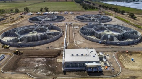
New nutrient removal plant for Melbourne Water completed
A new, innovative nutrient removal plant has been completed at Melbourne Water’s Western Treatment Plant—where around half of Melbourne’s...
-
$2.6 billion committed to QLD water infrastructure
The Queensland Government continues to deliver key water infrastructure, including the Haughton pipeline, to create jobs and support the...
-
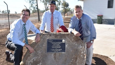
Gunnedah wastewater facility upgrade complete
Gunnedah’s Wastewater Management Facility has undergone an $8.1 million major remodel to future-proof Gunnedah’s sewerage treatment works until 2038....
-
$400k desalination trial to address WA’s drying climate
A $400,000 investment by the Western Australian Government will support the construction of three community desalination units, built to...
-
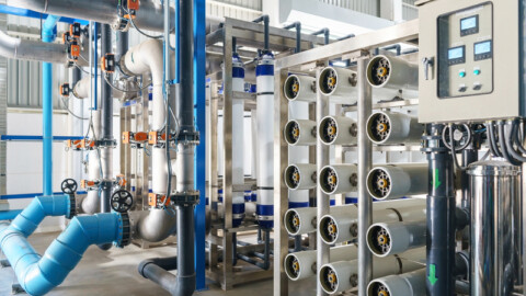
Meekatharra water treatment plant complete
The Meekatharra advanced water treatment plant has been completed, and will improve water quality in the Murchison area by...
-
New water treatment plant for Canungra
Seqwater will construct a new $4million Water Treatment Plant in Canungra (QLD) which will triple the capacity of the...


