


By Joe Evans, Pump Ed 101
Newcomers to the pump industry are often unfamiliar with many of the three phase motor starting techniques that employed “pre-semiconductor” technology. Surprise — most of them are still in use today and will probably be here for some time to come. The primary purpose of alternative starting techniques is to reduce the system loading during starting. The typical AC induction motor has an inrush current during starting that is about five to seven times that of run current. Today, the VFD can provide a soft start and stop automatically just by ramping the input frequency. In the past, it was not always that easy. This article will review the most common methods of motor starting. A table at the very end will compare the electrical characteristics of each.
Before we get started, let’s review how a typical six lead, three phase motor’s windings are connected to incoming power. The six lead stator is easiest to grasp and understanding how it is wired is important to our discussion of several starting techniques.
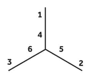
Figure 1: Dual voltage motor connection schemes.
 Single voltage motors can be designed for either Wye (Y) or Delta connections. Dual (and tri) voltage motors are usually designed to utilise a Wye connection for high voltage and a Delta connection for low voltage. Figure 1 illustrates these two connection schemes.
In the Wye connection (left hand figure), winding ends 4, 5 and 6 are joined together. Incoming power is connected to leads 1, 2 and 3 (the other end of the windings). In order for any two phases to connect electrically, they must traverse two sets of windings, thus increasing the impedance of the circuit.
In the Delta connection (right hand figure) winding ends 1 and 6, 2 and 4, and 3 and 5 are joined together. Incoming power is applied to each of these three pairs. Now any two phases may connect through a single winding. It is also common to find dual voltage motors wound for Y or Delta connection only. In this case, nine leads are required to establish the proper winding/voltage relationship.

Figure 2: Across the line starting
Across the line starting
The most common method of starting a motor is “across the line”. Here, a three pole switch or magnetic contactor connects line voltage directly to each of the motor leads. With this method, motor terminal voltage and current equals line voltage and current, and starting torque equals the motor’s rated starting torque. Figure 2 is a typical across the line starting schematic.
There are times, however, when it is desirable to reduce the current load required to start a motor, especially a large one. The following common, reduced current starting methods will accomplish this to varying degrees.

Figure 3: Series resistance reduced voltage
Series resistance reduced voltage starting
When series resistance starting is employed, a voltage-dropping resistance is placed in series with the motor during starting. Figure 3 illustrates this technique. The resistance increases the overall impedance which causes a voltage drop. This method is used in low voltage (under 600V) applications where torque, during acceleration, is minimal. It is also limited to smaller motors since heat loss in the resistors can be a factor with larger models. There are instances where the motor cable alone can provide the necessary resistance during starting. Submersible pump motors that employ the maximum recommended length of a particular cable size can expect a five per cent voltage drop during starting. This will result in a nominal 16–20 per cent reduction in starting current.
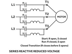
Figure 4: Series reative reduced voltage
Series reactance reduced voltage starting
Figure 4 shows a starting method that is similar to the one above, except that a voltage dropping reactance is substituted for the resistance. Again, overall impedance is increased and the result is a voltage drop. Series reactance starting is used on medium voltage and large low voltage motors with minimal torque loading during acceleration.

Figure 5: Autotransformer reduced voltage
Autotransformer reduced voltage starting
In this form of reduced voltage starting, an autotransformer is placed in series with the motor. Its schematic is shown below. The transformer reduces the line voltage and thus reduces starting current. Starting current reduction depends on the voltage output of the transformer. Usually these devices are configured with an 80 per cent, 65 per cent and 50 per cent output tap. They are used where the required current reduction is substantial and load torque can be high.
Solid state reduced voltage starting
This form of reduced voltage starting uses a solid state starter that incorporates SCR’s (silicon controlled rectifiers). The SCR’s reduce the AC sine wave amplitude so that only a portion of the wave is seen by the motor. They are controlled by logic circuits that can respond to several different feedback sensors. Solid state starters are used when the rate of acceleration must be controlled or when a “soft” start (reduced current) is desired. They are available
for both low and medium (4160V) voltage motors.

Figure 6: Solid state reduced voltage starting
Solid state variable frequency starting
Although sometimes confused with the method described above, variable frequency starting applies the full “effective” voltage to the motor terminals but at a reduced frequency via a variable frequency inverter. The initial frequency can be very low and increased gradually. It is often used when full load torque is required during acceleration. They are usually too expensive to be used just as a starter, but can be justified at times because they offer the very best starting characteristics relative to the burden placed on the power supply.
So far, we have discussed starting techniques that utilise devices that are totally separate from the motor. There are, however, several methods that can reduce starting current by changing the motor’s winding configuration.
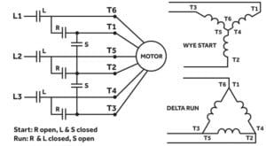
Figure 7: Wye start and delta run
Wye start/delta run reduced voltage starting
Technically this is not a reduced voltage technique in that the motor terminals see full voltage. The wye/delta starter connects the motor’s leads in a wye configuration during starting thus increasing the circuit’s normal reactance. The result is a decrease in voltage reflected to the stator equal to √3. Thus the current draw is reduced to about 30 per cent of the normal starting current.
Once the motor is running the starter switches the leads to a normal delta connection and full voltage is restored. This technique is used when very low starting torque is required and is seen more often in systems manufactured in Europe.

Figure 8: Part winding start
Part winding starting
This starting method requires a motor wound specifically for this application. It is not a reduced voltage technique. These special nine lead motors use only a portion (1/2 to 2/3) of their windings during starting. Starting torque is extremely low and the motor is not expected to accelerate. Under some conditions, the shaft may not undergo visual rotation. In any case the starter should not remain in the start position for more that one to two seconds because of potential heat damage to the windings.
The starting methods described here apply to three phase, AC induction motors. There are other starting techniques for wound rotor AC motors and they will be discussed in a separate tutorial. The table below summarises the electrical characteristics of the various starting techniques we have discussed.

Find Motors, Drives And Engines Related Companies In The Pump Industry Capability Guide


-
Selecting an irrigation pump
By Bill Yiasoumi, retired irrigation officer, NSW Department of Primary Industries Farmers can select from a wide range of...
-
Be recognised as a pump installation expert
Pump Industry Australia (PIA) is running an installation and commissioning course on 14 September at Link Pumps, which allows...
-
Pump station renewal boosting asset lifespan
By Kody Cook, Journalist, Pump Industry Magazine Northern Territory utility provider Power and Water has completed a refurbishment of...
-
Condition monitoring of multi-stage pumps by measuring the balance leakoff flow
By Ray Beebe, MCM Consultants and Federation University A previous article (Optimise overhauls of pumps to save energy, Pump...
-
Pumping up Dubbo’s assets
Dubbo Regional Council in New South Wales’ Orana Region has been undertaking a range of upgrades, and water and...
-
Slurry corrections for centrifugal pump performance
Correctly sizing and selecting a pump is crucial in any situation, especially when efficiency and cost considerations are in...
-
Automated waste collection at the heart of Maroochydore’s new CBD
A 53-hectare greenfield site in Maroochydore on Queensland’s Sunshine Coast is being transformed into a Central Business District for...
-
Perkins® My Engine App: taking service and capability to a new level
With Perkins recognised as one of the world’s leading diesel engine manufacturers, AllightSykes is proud to be the authorised...


