


A heating, ventilation and air conditioning (HVAC) piping system is designed to convey a heat transfer fluid to multiple air handlers, providing cooling (chilled water) or heating (hydronic heating) loads in a building. A typical HVAC system consists of a primary loop and a secondary loop. The primary loop contains the chiller or boiler along with primary circulating pump(s). The secondary loop draws fluid from the primary loop and consists of a secondary pump along with the supply header piping, various air handlers and return header piping. The primary and secondary loops are connected, so fluid mixes between the loops.
The key to designing an HVAC circulating water system is to control the flow rates to the various air handlers in order to maintain the temperature in the conditioned spaces. There are two types of methods to achieve this goal: one is a constant volume system, the other a variable demand system. In this analysis, you will learn how to achieve significant cost savings by using a variable demand system versus the more traditional constant volume system.
Modelling the system

Image 1: Modelled HVAC system (image courtesy of the author)
Before you design a new system, or make major modifications to an existing piping system, it is a good idea to create a computerised hydraulic model of the HVAC piping system. Piping software can provide the information needed to properly select the pumps and control valves. In addition, the computer model provides a good understanding of the interaction of pumps, pipelines and control valves.
The information from the computerised model can also be used to perform an economic analysis of pumping costs for both types of control systems. Image 1 is a rendering of a modelled HVAC system. To perform this analysis, look at the differences between constant volume control and variable demand control, and perform a pumping cost analysis for each.
Constant volume control vs. variable demand control
Under constant volume control for the piping layout in Image 1, both secondary pumps are operating just over 660 gallons per minute (GPM). Since this is a constant volume system, both pumps will be running constantly at this flow rate year-round. To keep the volume constant, some flow will go through the air handlers, and the remainder
will go through a bypass line.
In a variable demand system, the flow rates to the loads vary based on the required heating or cooling needs. The first requirement is to
estimate the required flow rates. They are based on the heating or air conditioning loads and may vary by the time of year and time of day.
In this analysis, it has been assumed that the average flow requirements in the winter months will be 30 per cent of the maximum design flow, spring and fall is 45 per cent of the maximum, and in the summer the design flow is 85 per cent of the maximum. It is important to note that the maximum design load is based on the needs for the
hottest or coldest day of the year.
Constant volume pumping costs
In this example for this project in the Pacific Northwest, the yearly pumping costs for the system was an energy rate of US8 cents per kilowatt hour (kWh). This should provide a conservative estimate elsewhere of costs as the national average is close to 13 cents per kWh.

Image 2: Yearly operating cost calculator results: constant volume (image courtesy of the author)

Image 3: Yearly operating cost calculator results: variable demand (image courtesy of the author)
Variable demand pumping costs
The variable demand costs are slightly more complicated as the loads will vary more throughout the year. Here, we are using the flow rates mentioned above and considering
summer, winter, spring and fall to each account for 25 per cent of the year. The spring and fall demands here are the same so they have been combined for a total of 50 per cent of the year.
The first important note here is that the system is capable of meeting the demands year-round using only one secondary pump. The operating costs for this secondary pump are $3080 in the summer, $140 in the winter and $560 in the combined spring and fall seasons for a total of $3780 for the year.
This annual operating cost for the secondary pumps is significantly less than the cost associated with the constant demand system. It is important to note that the reduction in pumping cost can only be brought about by installing a variable frequency drive (VFD). It is also important to factor in the cost of the VFD in your lifecycle pumping cost calculations.
Constant volume system
The constant volume system is the more traditional method in which the system is balanced, such that a constant volume of fluid is flowing to each air handler regardless of the load. The piping to the air handler consists of a three-way valve that directs flow to the air handler or to a bypass line (Image 4).
In a constant volume system, the combined flow in the bypass line and to the air handler is constant, regardless of the flow rate to the air handler. A three-way valve directs the fluid through the bypass line, unless there is a demand on the air handler. When a demand is placed on the air handler, the three-way valve is repositioned to send some fluid to the air handler and less fluid through the bypass line. When there is no longer a demand by the air handler, the three-way valve redirects the flow through the bypass line.

Image 4: Typical constant volume circuit (image courtesy of the author)
The major advantage of the constant volume design is that once the system is balanced, by setting the design flow rate to each load, the control system is very stable. The three-way valve is able to direct the flow to the air handler without affecting the total flow rate through the system.
The major disadvantage to the constant volume system is the flow rates to each air handler are the same year-round regardless of the system’s heating or cooling load. In other words, in an HVAC chilled water system, the flow rate through the secondary loop is the same for the coldest day of winter as it is for the hottest day of summer. Therefore, constant volume systems typically have a higher operating cost because the flow rate through the secondary system is the same regardless of the system load.
Variable demand system
Now that energy costs are higher, variable demand systems are becoming more popular. On a variable demand system, the three-way valve and bypass line are replaced with a pressure reducer and control valve in series to regulate flow to the air handler (Image 5). As the control valves in the other loads regulate the flow rate through the various paths, the differential pressures across the control valve can vary considerably. The wide variation of differential pressure across the control valves due to changes in system loads could cause problems with the control valve.
To overcome this problem, a pressure regulator is placed upstream of the flow control valve to absorb some of the excess differential pressure between the supply header and
return header. The job of the pressure regulator is to reduce the pressure drop across the control valve. A smaller valve actuator can then be used so that a finer control can be achieved.
Using a variable demand system saves on the operating cost because the flow rate through the system varies to meet the needs of the system demands rather than maintaining a
constant system flow rate.

Typical variable demand circuit (image courtesy of the author)
Greater pumping cost savings can be achieved on a variable demand system by adding a VFD on the pump. As mentioned previously, a pressure regulator is typically placed upstream of the control valve to limit the maximum differential pressure across the control valve. That is because as the flow rates in the other paths decrease, the pump moves back on its pump curve and provides a greater differential pressure across the pump.
This results in a greater differential pressure across the supply and return headers. The job of the pressure regulator is to absorb some of the excess differential pressure so that the control valve can operate properly.
By installing a variable speed drive and controlling the pump’s speed based on the differential pressure across the various control valves, the pump produces less head for the same flow rate. This results in a lower differential pressure across the pressure regulator. Since the pump head is less, the pump consumes less energy, resulting in further savings in pumping cost.
It is important to remember that there needs to be a minimum differential pressure across each control valve for the valve to operate properly. The purpose of the variable speed drive is to slow down the pump to provide only sufficient head needed for the control valves to operate properly. There is usually one control valve in the system that has the lowest differential pressure, and this is referred to as the most hydraulically remote control valve.
A differential pressure sensor can be installed across the most hydraulically remote control valve to control the pump speed. One additional point to remember; based on the various load combinations to the air handlers, the most hydraulically remote control valve in the system can change. Therefore, additional differential pressure sensors may be needed, resulting in additional instrumentation.
Since there may be many loads in a large HVAC system, it can become cost-prohibitive to insert differential pressure instrumentation on each control valve in the system. It is more cost-effective to install the differential pressure controls only on the valves in the system that have the possibility of the lowest pressure drop. This requires a thorough understanding of the HVAC piping system.
Find Building Services Related Companies In The Pump Industry Capability Guide


-
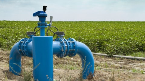
Measuring pumping costs for electric irrigation pumps
If the wrong pump is chosen or is worn out, this can increase pumping costs and reduce productivity. In...
-
EU legislation has major impact on pump sector
By Steve Schofield, Director and Chief Executive of the British Pump Manufacturers’ Association (BPMA) In 2006 the European Commission...
-
SimScale: engineering simulation to the valve industry
The first cloud-based simulation platform in the world is transforming the CAE field Industries worldwide have an increased demand...
-
Failing the test
What happens when a fire hydrant system is left unmaintained and unserviced? When subjected to a routine hydrostatic test, they...
-
Tender: HVAC equipment maintenance and repairs
Public Transport Authority (WA) is seeking tenders for the supply, installation, maintenance and repair services to heating, ventilation and...
-
Tender: air-conditioning maintenance
Logan City Council Council (QLD) is currently seeking offers from suitably qualified contractors for a preferred supplier arrangement for...
-
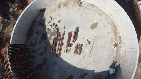
Installing Bendigo’s biggest valves to cater for future growth
In mid-September, Coliban Water completed works to install two huge 900mm valves on a water main in Golden Square,...
-
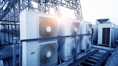
Fans in industrial applications
By Dr Simon Bradwell, Fan Manufacturers Association and ebm-papst A&NZ Big cooling tasks need great technology, at the highest...


