


by Ron Astall, PIA President
Regular readers of Pump Industry will be familiar with Ron Astall’s popular series of articles on understanding pump curves. After a brief hiatus, Ron is back to explain how to select for unusual running speeds.
 This article describes how we can use standard centrifugal pump catalogue curves to select for other running speeds. For example you may have a low head application and suspect that an 8 pole operating speed may suit – but the catalogue that you have only shows 2 pole and 4 pole speeds, and there is no range chart for 8 pole speed either.
Poles?
Most centrifugal pumps are driven by simple, rugged and reliable squirrel cage induction electric motors, which run at essentially a constant speed. Their speed depends on the number of poles in the motor and the electric supply frequency; usually 50Hz or perhaps 60Hz as in the Americas and some parts of Asia.
For electric motors we are stuck with the typical fixed speed options as shown below:
Available motor speeds
Pump Running Speed – RPM (assuming typical 20 RPM slip)
| Number of Poles | 50Hz supply frequency | 60Hz supply frequency |
| 2 | 2980 | 3580 |
| 4 | 1480 | 1780 |
| 6 | 980 | 1180 |
| 8 | 730 | 880 |
| 10 | 580 | 700 |
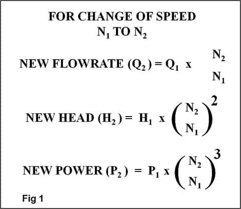
Affinity Laws
As discussed in a previous article on variable speed, the performance of a centrifugal pump at different speeds can be predicted by the Affinity Laws as per Figure 1.
We can use these Affinity Laws in reverse to modify our flow and head to suit the speed of the available performance curves and range charts. Sound confusing? Not really. Let’s work through an example.
 Let’s say we need to select a pump for a flow and head of 80L/s at 10m. For such a low head, it is likely that a low running speed will be involved. If we look at the 4 pole (1,470rpm) range charts (Figure 2) we can see that there is no pump selection matching this flow and head at 1,450 rpm.
It is logical to predict that if we were to run the pumps in the range chart at an even lower speed, say at 8 pole (730rpm), there ought to be a selection available. So let’s assume that there is available a hypothetical pump running at 730rpm that would suit our duty of 80L/s at 10m head.
We will now calculate what would happen if we were to speed this hypothetical pump up to 4 pole (1,480rpm) using the Affinity Laws. Going from 8 pole to 4 pole is theoretically doubling the speed, so we will ignore differences in motor slip and assume a 2x speed change. From the Affinity Laws, doubling the speed will double the flow. The head will increase by the speed change squared (22 = x 4). See Figure 3.
What we have done is calculate what an imaginary 8 pole speed pump selected for our duty of 80L/s at 10m would produce if operated at 4 pole speed. Now we can go back to the 4 pole range chart to see if this ‘speeded up’ duty corresponds to an actual pump. See Figure 4.
Sure enough – yes it does; we have a selection for a 250 x 250 – 400 pump. This tells us that this pump will do the duty we want when slowed down to 8 pole speed.

Final selection
From the range chart we can now go to the actual pump curve at 4 pole speed and confirm the selection. We can mark the equivalent 4 pole operating point on this curve and then use the Affinity Laws to estimate the efficiency, power consumption and NPSHR for 8 pole (730rpm) operation. See Figure 5.
In this example the actual running speed will be half of the curve speed so from the Affinity Laws, the estimated power at 8 pole speed will be one eighth of the 4 pole curve. NPSHR theoretically follows the same Affinity Laws as for head and is thus estimated at a quarter of that of the 4 pole curve.
Other speeds and examples
I have chosen the particular example of selecting a pump for a 8 pole running speed, but the principle is universal. Using the Affinity Laws, you can ‘adjust’ any proposed pump duty to allow initial selection from available standard range charts and curves. Other examples include selection for engine drives or using 50Hz curves to select for 60Hz service. A few more examples are shown in the table below:

Be careful!
Using the Affinity Laws in this way is great for the initial selection process, but these laws assume that pump efficiency does not change with speed. Efficiency correction factors may apply and the NPSHR prediction may not always be that accurate.
 The pump manufacturer should ultimately be consulted to confirm pump performance at the final running speed and to confirm the impeller diameter.
When selecting pumps for a speed higher than the published curve, it is critical that the pump design be checked as being suitable for the higher power and pressure ratings that will result.
 The above is a useful tool that allows us to select centrifugal pumps using available range charts and curves when published curves are not available at the intended running speed. However, care must to be taken to confirm actual performance and suitability once the initial selection has been made.
Find Motors, Drives And Engines Related Companies In The Pump Industry Capability Guide


-
EnergyAustralia’s Tallawarra B gas/hydrogen energy project on track
The Tallawarra B gas/hydrogen power project is set to be commissioned by the end of 2023, following the completion...
-
Vineyard saves fuel with efficient irrigation pumping
Located in NSW’s Griffith region, Farm 8a Benerembah is a 165 ha property, producing a wide range of grape...
-
Re-assessing lifetime lubricated sealed bearings
by Heinz P. Bloch, PE, Process Machinery Consulting Bearing lubrication is an essential component of proper motor maintenance. Here,...
-
System troubleshooting quiz: Can you identify the problem?
System troubleshooting can be a difficult process for even the most experienced professionals and securing the necessary data to...
-
Glossary of pump terms L-Z
Brown Brothers Engineers Australia Pty Ltd A-K Glossary of pump terms here L Labyrinth seal: A non-contacting seal utilising...
-
Pumped hydro storage final design
Genex Power has selected a design for its new pumped storage hydroelectric power plant it is developing at the...
-
33 new models introduced to Caprari’s K+ Energy submersible pump range
To meet the needs of the operators in the wastewater industry, who are increasingly concerned with energy efficiency, and...
-
Sewage pump station upgrade
TasWater plans to construct a new sewage pump station for George Town (TAS) to replace the existing station due...


