


By Dr Paul Huggett, Principal, Materials Solutions Pty Ltd
Current trends with tailings pumping often require transportation along relatively long distance pipelines. Combined with the presence of a high solids concentration, the slurry will have a high viscosity and will have a significant effect on the discharge head required for pumping. In order to more accurately determine the pipeline friction losses, it is essential to conduct slurry rheology tests on tailings samples. The rheology testing will provide information relating to the slurry viscosity at varying solids concentration, from which we can calculate the pipeline friction losses. Successful use of the right data will minimize errors in the design and selection of pipelines and pumping equipment. This brief article will provide a summary of the types of rheology testing that can be conducted, and how we use the data to determine the pipeline friction losses.
Basic Slurry Rheology
All fluids have a specific viscosity, and the value of the viscosity will change with variations in properties such as temperature, concentration and in the case of pumping the amount of shear applied to the fluid. Fluids can be classed as having a Newtonian viscosity relationship if the viscosity is constant for changes in shear rate, or a number of other non-Newtonian types of viscous fluids, as depicted in Figure 1.
Most slurries, which are typically mixtures of solid particles and water, will typically behave as Newtonian slurries when the solids concentration is below 40 to 45 weight%. As the solids concentration is thickened in modern mineral processing plants to minimize water discharge to tailings storage facilities, the slurries behave as other viscous mixtures, and either the Bingham or Hershel-Bulkley models are used to determine the pipeline friction losses.
Slurry rheology is measured by using a few different test methods, including rotating viscometers (Fig 2), capillary tube viscometers (Fig 3), and slurry loops. All of these types of tests measure the slurry shear stress at varying shear rates, and the resulting data is then plotted on a graph to view the shape of the curve as shown in Fig 1.
Weir Minerals have published an excellent guide to understanding the relationships between slurry viscosity and friction losses in pipelines [Ref 1]. This guide gives examples of how to calculate slurry friction losses for different flow regimes, known as laminar or turbulent flow. Laminar flow occurs at low shear rates, whilst turbulent flow occurs at high shear rates, and approximates more closely the friction loss model for Newtonian fluids.
Once the slurry rheology testing is complete, a series of shear rate/shear stress curves will have been generated, as shown in Fig 4. The various curves can then be modeled using mathematical regression analysis to provide a generalized formula or numerical expression for the calculation of the yield stress and viscosity values for any given solids concentration.
For a slurry pipeline, the shear rate within the pipe for a given flow rate is calculated from the expression:
Shear Rate,γ=(8.vel)/d (Units of 1/s) Equ. 1
where:
vel = slurry velocity (m/s);
d = pipe inside diameter (m)
The shear stress is calculated for a given shear rate based on the mathematical model, in this case the Herschel-Bulkley model, which has the form:
Shear stress= τ0+K.γn (Units of Pa) Equ. 2
where:
τ0=Yield stress(Pa);
γ=shear rate(1/s);
K and n are constants.
The apparent viscosity for a slurry at a given flow rate is then calculated from the ratio of shear stress divided by the shear rate, with units of Pa.s.
When the slurry flow is in the lamella zone, the shear stress can be used to calculate the pipe segment friction loss.
When the slurry flow is in the turbulent zone, the apparent viscosity is used to calculate a modified slurry Reynolds number, which in turn is then used to calculate the equivalent Darcy friction factor for the viscous slurry.
One of the advantages of using a slurry pipe loop to measure rheology is the measured pipe pressure loss values can be directly scaled to larger pipe systems, and the true change in shear stress as the flow increase through the pipe is shown. Using rotational viscometers, the shear stress relationship for pipes in the turbulent flow situation is not adequately expressed. An example of rheology test results from a slurry loop are shown in Fig 5.
Example Application of Slurry Rheology for a Tailings Pipeline
An iron ore processing plant located in the Pilbara Region of Western Australia was undergoing a raise in the wall height for the storage facility to increase the long term capacity. A series of slurry rheology tests had been conducted and a relationship of slurry shear rate and shear stress values were determined.
The data was processed to produce a mathematical model relating slurry viscosity to the solids concentration.
The tails pipe line at the mine site discharged to a location approximately 7.5km from the mine processing plant. The tails pipeline consisted of a polyurethane lined steel pipe, of nominal 300mm diameter.
In the example of the iron ore mine in the Pilbarra, slurry flow at approximately 40 weight % solids follows a Newtonian slurry calculation, and when the slurry is thickened to the target concentration of 50 weight % solids, the slurry has a significantly higher viscosity. A photo of the installed pipeline is shown in Fig 6.
Slurry calculation based on the Herschel-Bulkley rheology model, and also standard Newtonian slurries were calculated for the various planned duties. The 3D pipe route and resulting pipe pressure profile is shown in Fig 7. The pipe pressure is required to be greater than the static head at any point along the pipeline.
The change in slurry viscosity for the higher solids concentration results in the total pumping head of approximately 124 metres, requiring two stage pumping. In this application, Weir Warman 6FHP high head pumps were selected for the two stage duty, each pump installed with a 280kW, 6 pole direct coupled electric motor. A second set of Krebbs Mill-max pumps were also installed for comparison trials and are shown in Fig 8. The pump duty point for the Weir Warman pump is shown in Fig 9.
As part of the design process for this tails pipeline and pumping study, the existing tails duty was used to model the system, and a close correlation was found between the calculated system head loss and the actual pump discharge pressures. Having a close correlation between the calculated and measured duty provided a higher level of confidence when the final pumping duties were selected.
Summary
Mining tails pumping often involve viscous slurries that have varying properties depending on the solids concentration. It is essential when conducting long distance pumping studies the slurry rheological properties are measured to enable more accurate modeling of the pipeline friction losses. Ideally slurry pipe loops should be used to measure the slurry rheology. Rotational viscometers and capillary tube viscometers will provide similar data, however the slurry loop provides a better understanding of the turbulent flow areas for the slurry.
Care should be taken when calculating slurry pipeline friction losses for varying solids concentrations as the slurry behavior can often change from viscous non-Newtonian to more standard settling slurries at lower solids concentrations.
It is important to understand that viscous slurries can also be settling in nature. Conventional theory tends to treat viscous slurries as non-settling, however even very viscous slurries may exhibit some degree of particle settling if the pipeline is allowed to operate at very low flow rates.
References:
1. “Pumping Non-Newtonian Slurries”, Weir Minerals Technical Bulletin No. 14, Ver 2, August 2009.
-
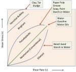
- Fig 1: Types of viscous slurries
-
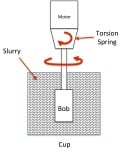
- Fig 2: Typical Rotating Viscometer
-
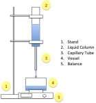
- Fig 3: Capillary Tube Viscometer
-
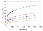
- Fig 4: Series of shear rate vs shear stress curves for varying solids concentrations
-

- Fig 5: Example of slurry rheology test results from a pipe loop.
-

- Fig 6: Iron ore tails pipeline
-
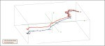
- Fig 7: 3D representation of tails pipeline. (Pump station located at bottom left of route).
-

- Fig 8: Two stage Krebbs Mill-Max tails pumping station used for iron ore tails duty
-
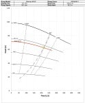
- Fig 9: System resistance curve and pump duty point for iron ore tails
About the author
Paul Huggett is the Principal Scientist/Engineer & Director at Materials Solutions Pty Ltd. Paul has over 25 years of experience and knowledge of engineering design and materials for manufacturing, mining and mineral processing industries. Areas of expertise include project management and design engineering of mining based projects, including mineral processing plants, surface and underground infrastructure, mineral processing systems and mine dewatering systems.
Paul has worked on a number of overseas projects, including Obuasi Gold Mine (Ghana), Syama Gold Mine (Mali), Gosowong Gold Mine (Indonesia), Mt Muro Gold Mine (Indonesia), and Pt Koba Tin (Indonesia) and is a specialist in slurry and water pumping, hydraulics, rheology testing and troubleshooting. A major portion of work is providing specialist design engineering for tailings pumping systems for mining operations.
Other areas of interest include the research and development of specialist wear materials, and Paul has an extensive knowledge of materials and materials related to manufacturing including metal alloys, ceramics, polymers and composites.
Find Slurry Pumps Related Companies In The Pump Industry Capability Guide

-
EHEDG certification for progressive cavity pumps
The pump industry relies on expertise from a large and varied range of specialists, from experts in particular pump types...
-
Queensland’s Carmichael project progresses
The $21.7 billion Carmichael project in the Galilee Basin, Queensland has received all required primary approvals and can soon...
-
The use of protective coatings on pump components
by Hugo Howse, United Surface Technologies In a previous article (‘Wear protection of pump components using hard coatings’, Pump...
-
SAER expands its range of IR close coupled pumps
IR pumps are one of the most known and appreciated series of the Italian manufacturer SAER ELETTROPOMPE. SAER has...
-
Understanding pump curves #5 : Minimum flow – part one
Ron Astall, United Pumps Australia Ask ten different pump engineers for their guidelines on establishing centrifugal pump minimum flow...
-
Top reasons for pump seal failure and how to avoid them
Pump seal failure and leakage is one of the most common reasons for pump downtime, and can be caused...
-
ABB gets automation contract for Anglo American’s Grosvenor coal mine
Power and automation technology group ABB has won an order worth US$38 million to design, engineer and supply an...
-
Understanding pump curves #8 : Are your pumps running too slowly? (Part Two)
by Ron Astall, United Pumps Australia In the last article we discussed the dangers associated with arbitrarily specifying pump...


