

by Ray Hardee, Chief Engineer, Engineered Software
In this article, we will look at a wastewater collection system consisting of a pump, collection and destination tanks, and the interconnecting piping. In this system, water is pumped from a collection tank to the destination tank and a pump is required to overcome the change in static head caused by the change in liquid level in the tanks and the piping head loss in the interconnecting piping. We will outline the tasks that must be performed when selecting the system equipment needed to meet the system design requirements. This process can be followed when designing a new system or modifying existing systems undergoing major changes from the initial design.
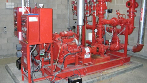
Sample waste transfer pump system

Figure 1 – This example system is made of pump elements, process elements, and control elements. We will see how all these elements work together to meet the system design requirements.
Determine the system requirements
Every piping system is designed to meet a specific need. The first step is to determine the process fluid and the system’s design flow rate. Since this is a municipal waste collection system, the process fluid is water at 15°C.
The system is designed for a maximum flow rate of 90m3/hr. Figure 1 shows the collection and destination tank elevations and working levels. From this information we can start the design process. As always, we will look at selecting the various elements making up the system.
The process elements
In our example the two tanks and interconnecting piping comprise the process elements. The collection tank serves as the inlet boundary, and the destination tank serves as the outlet boundary.
The physical layout determines the location of each tank, along with the working level of fluid in each tank. The difference in the liquid level and pressures between the two system boundaries represent the system static head that must be overcome.
The process fluid and its operating temperature determines the pipe material to be used. The working pressure of the process fluid is used to determine the required pipe wall thickness. The system design flow rate along with the pipe material and wall thickness is needed to determine the pipe diameter.
The operational requirements of the system determine the number and type of valves and fittings required for each pipeline so the resulting system can be efficiently operated and maintained.
Once the pipeline design requirements are determined, the dynamic head loss for the interconnecting piping can be calculated for the design flow rate.
The control elements
In this system, control elements are used to operate the pump and turn the pump off when not needed. This can be accomplished by a manually operated on/off switch or automated controls so the system can meet its design goals. In this system, level switches in the collection tank are used to control the pump.
The pump elements
With the system’s process and control elements determined, the designer can select the pump elements. Since this is a municipal waste collection system, the customer has determined to use a submersible centrifugal pump. With the system’s design flow rate and the total head requirements needed by the process and control elements, a pump can be selected using available pump selection software to meet the system’s design requirements.
What’s missing?
The method outlined above is commonly used when designing process systems. Based on the capital cost or special operating requirements, additional steps may be required to size specific elements.
In my experience, each of the basic elements are handled by specific groups. Process engineers focus on the process elements and system operation. The mechanical group focuses on pumps, the electrical group focuses on motors and electronic variable frequency drives on the pump elements.
The controls group focuses on the system instrumentation and control equipment needed to monitor and control the system. If one does not consider the interaction of the various elements on the total system, the design can result in increased operating and maintenance costs.
System operation
In our example system, the system flow rate was based on a maximum inlet flow rate of 90m3/hr into the collection tank. Based upon the customer’s operating experience, the maximum inflow to the collecting tank occurs for approximately one per cent of the system’s total operating hours.
The normal flow rate into the collection system of 45m3/hr occurs approximately 65 per cent of the annual operating hours. During off-peak hours, the rate into the collection system is 20m3/hr, which occurs approximately 33 per cent of the annual operating hours.
Selecting the pump to handle the maximum possible inflow into the collection tank ensures the tank will never overflow regardless of initial liquid level. With these further details of the system operating conditions, one can look for ways to improve the design to minimise operating and maintenance costs.
Ways to improve the system design
The pump elements
There are a variety of pump options that can be employed to improve the system design. Instead of selecting a single 90m3/hr pump to operate all the time, you could use two 45m3/hr pumps operating in parallel when maximum flow is needed. For the remainder of the year, a single 45m3/hr can meet the system’s requirements.
Purchasing two smaller pumps will cost more than a single larger pump, resulting in an increase in capital cost.
Furthermore, operating a single 45m3/hr pump increases the number of hours a pump must run in a year, however, the primary pump in operation can be optimised around the 45m3/hr design point.
By analysing both single pump and parallel pump configurations using system simulation software, you can easily calculate the power required at each of the operating conditions (maximum inflow, normal flow, and off-peak flow).
The system model can also account for the efficiencies gained from continuous operation around the best efficiency point, ensure minimum flow limits are not violated, and NPSH is maintained. From the pump power in each operating condition and the per cent of operation for each condition annually, a detailed operating cost calculation will determine the extent of the energy savings available.
Further analysis with time simulation will allow evaluation of the cycling required in each of the configurations, and its impact on the pump’s operating point. This evaluation can provide some insight into potential maintenance issues due to continuous, sub-optimal pump operation.
Even though the smaller pump takes twice as long to pump down the collection tank and is likely to incur higher capital costs, the total system is likely to consume less power when running and incur less maintenance.
The process elements
Looking at the dynamic head loss in the system, increasing the pipe diameter reduces the fluid velocity in the pipelines, resulting in a reduction in dynamic head. Increasing the pipe diameter results in an increase in the capital cost, but will reduce the system lifetime operating costs.
A cost comparison can be easily conducted to determine the extent of the savings. An additional benefit occurs if the system capacity will be increased in the future.
In looking at the example system, the system’s static head accounts for much of the pumping requirements. If possible, relocating the tank’s base elevation or adjusting the tank liquid operating level to reduce the system’s static head will also minimise the pump’s head requirement.
The control elements
The system is controlled using level switches in the collection tank. On a high liquid level, the wastewater pump is turned on. The pump continues to operate until the tank liquid level reaches the low level, at which time the pump is turned off.
One way to improve the system is to replace the on/off level switches with a level controller. Since flow rate in the system varies from 20m3/hr to 90m3/hr, a variable speed drive can be connected to the level controller. The pump speed is then automatically adjusted to maintain a consistent level in the collection tank.
The extra capital cost of the level controller could easily reduce the total lifetime cost for system operation. For analysis of this system design change, you will need a tool which can account for time-dependent inputs and control logic. This type of simulation over time will allow for the assessment of pump cycling as well as pump power.
Conclusion
By understanding the interaction of the various elements in a piping system, one can consider options for reducing a system’s lifetime cost. Since these design options can be easily evaluated using a system simulation program, optimising around the full set of system requirements can pay a huge dividend in reducing total system costs.


