


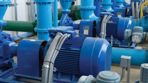
The primary role of a coupling is to join the rotating pump shaft to the drive shaft of the motor, which allows it to efficiently transmit power to the pump. However the right coupling in the right application can also offer plenty of advantages, including accommodating misalignment between shafts, permitting axial adjustment, vibration dampening, and absorption of shock loads. Here we look at the two main types of couplings, and explore their individual benefits.
Pump couplings can be organised into two overarching categories: rigid and flexible couplings. In general, rigid couplings are best suited to applications in which a solid connection between two shafts is desired. They can handle high precision and torque, but typically don’t offer misalignment absorption capabilities. Some common cases where you can find a rigid coupling are in vertical turbine, vertical in-line and short set pump applications.
Conversely, flexible couplings are typically used in applications where compensation is needed for misalignment, movement or deflection. As the name suggests, they are much better at accommodating axial, parallel and angular misalignments and are better suited to reducing transmission of shock loads or vibration. However, they offer less torque transfer than their rigid counterparts and are less suitable for applications where precision is vital. Flexible couplings are often selected for horizontal, base plate and mounted pump applications.
Rigid couplings
Although rigid couplings are the most basic, they are also often the most cost effective and their simple structure makes for easy assembly and maintenance. The most common configuration for rigid couplings are flange, sleeve, clamp, ring, set screw and spline couplings.
Flange couplings
Flange couplings consist of two flanged hubs that are joined by a bolted pattern that allows for perfect alignment of the two hubs. This type of coupling are designed for heavy duty applications. For this reason they are often found in pressurised piping systems where two pipes need to connect.
Sleeve couplings
The simplest type of rigid coupling, sleeve couplings consist of a hollow cylindrical sleeve keyed to the shafts to be connected. These couplings are used when the two shafts are perfectly aligned, and are not recommended for high power transmission or high speeds.
Spline couplings
Like sleeve couplings, but there are slots on the inner diameter of the sleeve that correspond to the same number of slots on the shaft’s outer side. This allows them to sustain high rotational speeds and remain largely insensitive to overloading.
Clamp couplings
Used to connect shafts of the same diameter, clamp couplings are designed for quick and easy installation and removal. These couplings consist of two half cylinders that clamp on the ends of shafts and are held together by steel bolts and use just one key over the whole length.
Ring compression couplings
This coupling configuration consists of two cones that are placed on the shafts and a sleeve that fits over these cones. Three bolts are used to draw the cones towards each other and wedge them firmly between the shafts and the outer sleeve.
Set screw couplings
Set screw couplings are comprised of a cylinder that is attached to the shaft using screws that impinge upon the shaft, and often also include a keyway for keyed shafts, which gives additional capacity to transmit torque. However, they can loosen under vibration.
Flexible Couplings
Flexible couplings is an umbrella term that covers any coupling that can accommodate some degree of movement between the shafts, and can also be used for reducing vibration and noise. There are generally three categories that flexible couplings fall under: mechanically flexible, material flexible and non-contact magnetic.
Couplings that are mechanically flexible utilise parts that are designed to roll or slide against each other to compensate for misalignment. Some examples of these are grid and gear couplings
Grid couplings
Grid couplings involve two toothed hubs that are joined by a hi-tensile metal grid spring element, which transmits the torque between the two shafts. The high torque density is the main benefit of this style of coupling, and its design allows the grid to be easily changed without removing the hubs. However it has limited ability to accommodate misalignment and as it is grease lubricated it requires ongoing maintenance.
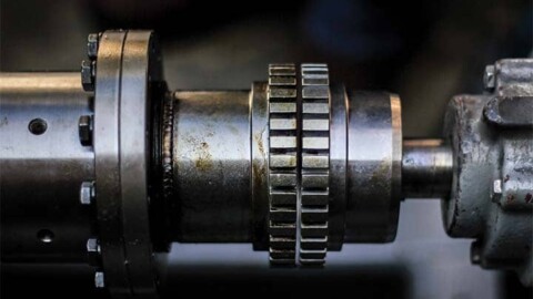
Gear couplings
A gear coupling is comprised of two metal hubs with external gear teeth that engage with teeth in the sleeve. This type of coupling can handle very high torque and has excellent misalignment capability. It is well-suited to extremely high loads and is often the coupling of choice for high torque drives. In material flexible couplings, it’s the coupling element itself that flexes to compensate for misalignment. Some common examples are:
Jaw couplings
These couplings have intermeshing jaws on each hub that fit into an elastomeric spider that is responsible for torque transmission. This solution is relatively cost-effective thanks to its replaceable rubber elements and cast iron hubs and is disposed of and replaced rather than maintained. It is well suited for transmission of shock loads and can dampen reactionary forces and vibration.
Shear in place couplings
Similar to jaw couplings but designed so the hubs are separated. In the event of an element failure, the driving hub disengages from the driven, spinning freely to avoid motor or pump damage.
Tyre couplings
In the past these couplings were often made from rubber, which made them cumbersome and increased the axial loads on the bearing.
However modern iterations utilise split urethane elements and variable spacer lengths to make this one of the most versatile economic coupling choices. These couplings are resistant to a lot of chemicals and inert to water.
Disc couplings
Disc couplings transmit torque between a driving to a driven bolt through a series of thin, stainless steel discs assembled in a pack.
These couplings are all-metal and have replaceable disk packs, resulting in little to no maintenance and a strong ability to handle high torques and compensate for misalignment. Popular in the oil, gas and petrochemical industries.
Diaphragm couplings
These couplings involve two diaphragms with an intermediate member between them. They are quite versatile and can accommodate for multiple angles of misalignment and can transmit torque at high speeds without the need for lubrication. They are often found in turbines, compressors, generators and aircraft.
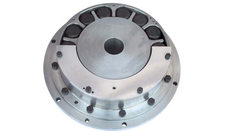
Non-contact magnetic couplings
Magnetic couplings use a magnet to couple the pump to the motor, which creates a small air gap between the magnet and the two components. This lack of physical contact means that misalignment and thermal expansion do not pose a problem. As there is also no mechanical seal involved this type of coupling also eliminates the risk of leakages, which is ideal for hazardous liquids. However, any particles present in the liquid it is handling can stick to the magnet. They are also not well-suited to excessive torque, and this can cause the magnets to decouple and the pump shaft to slip.


